Method and means for controlling the operation of a machine based upon the wearing apparel by the machine operator

a technology of machine operator and operation method, which is applied in the direction of frequency-division multiplex, multiplex communication, instruments, etc., can solve the problems of cumbersome use of mechanisms, special mats, shoes, or other equipment, and add additional hazards to the machin

Active Publication Date: 2005-02-15
STORK TOWNSEND BV
View PDF14 Cites 41 Cited by
  • Summary
  • Abstract
  • Description
  • Claims
  • Application Information

AI Technical Summary

Benefits of technology

The present invention is method and a machine using said method that uses sensors in a control circuit to prevent the machine from operating unless the operator is wearing proper protective apparel. The machine also ensures that the protective apparel is in the correct position before...

Problems solved by technology

These devices require the use of mechanisms, special mats, shoes, or other equipment that is cumbersome, expensive and unreliable.
These safety devices give a false sense of security to the operator and can add additional hazards to the machine.
Furthermore, prior art has mai...

Method used


Image

  • Method and means for controlling the operation of a machine based upon the wearing apparel by the machine operator
  • Method and means for controlling the operation of a machine based upon the wearing apparel by the machine operator
  • Method and means for controlling the operation of a machine based upon the wearing apparel by the machine operator

Examples


Embodiment Construction

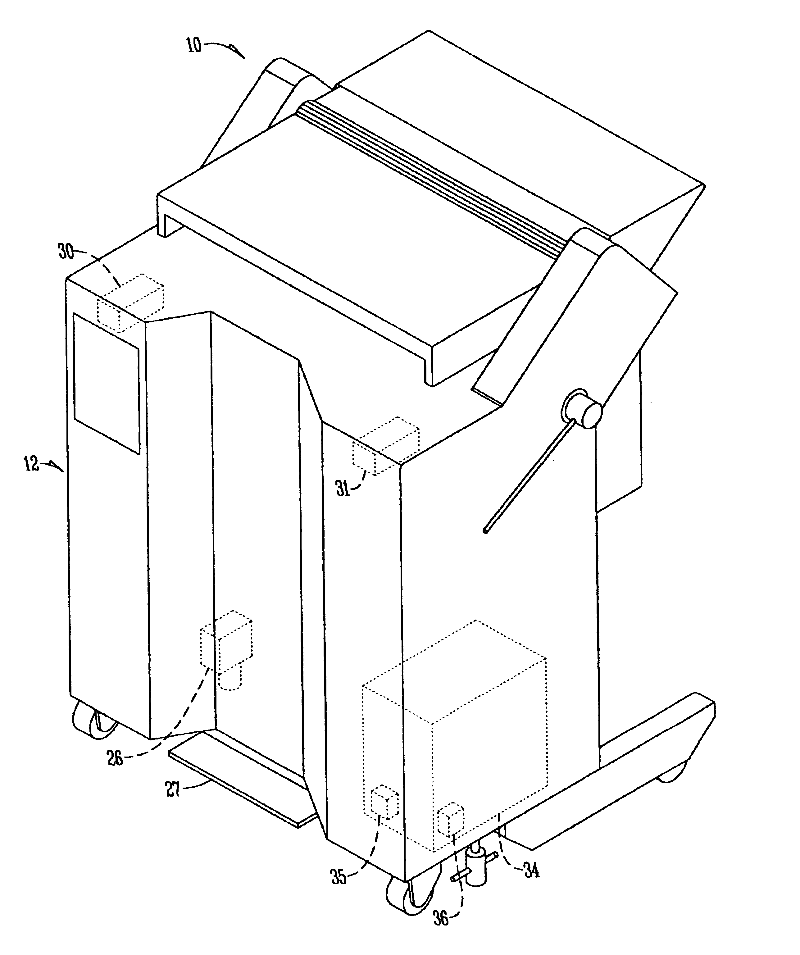
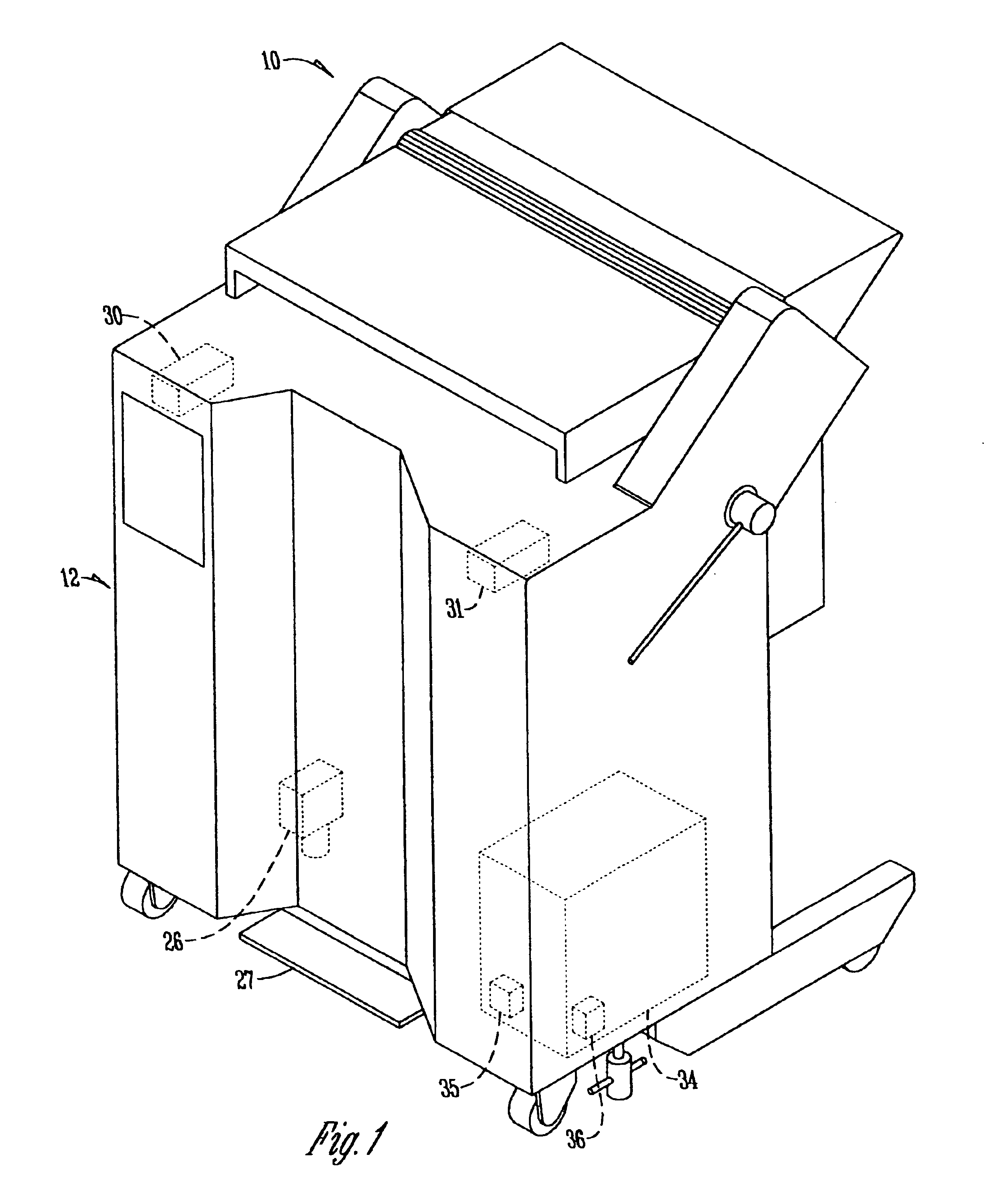
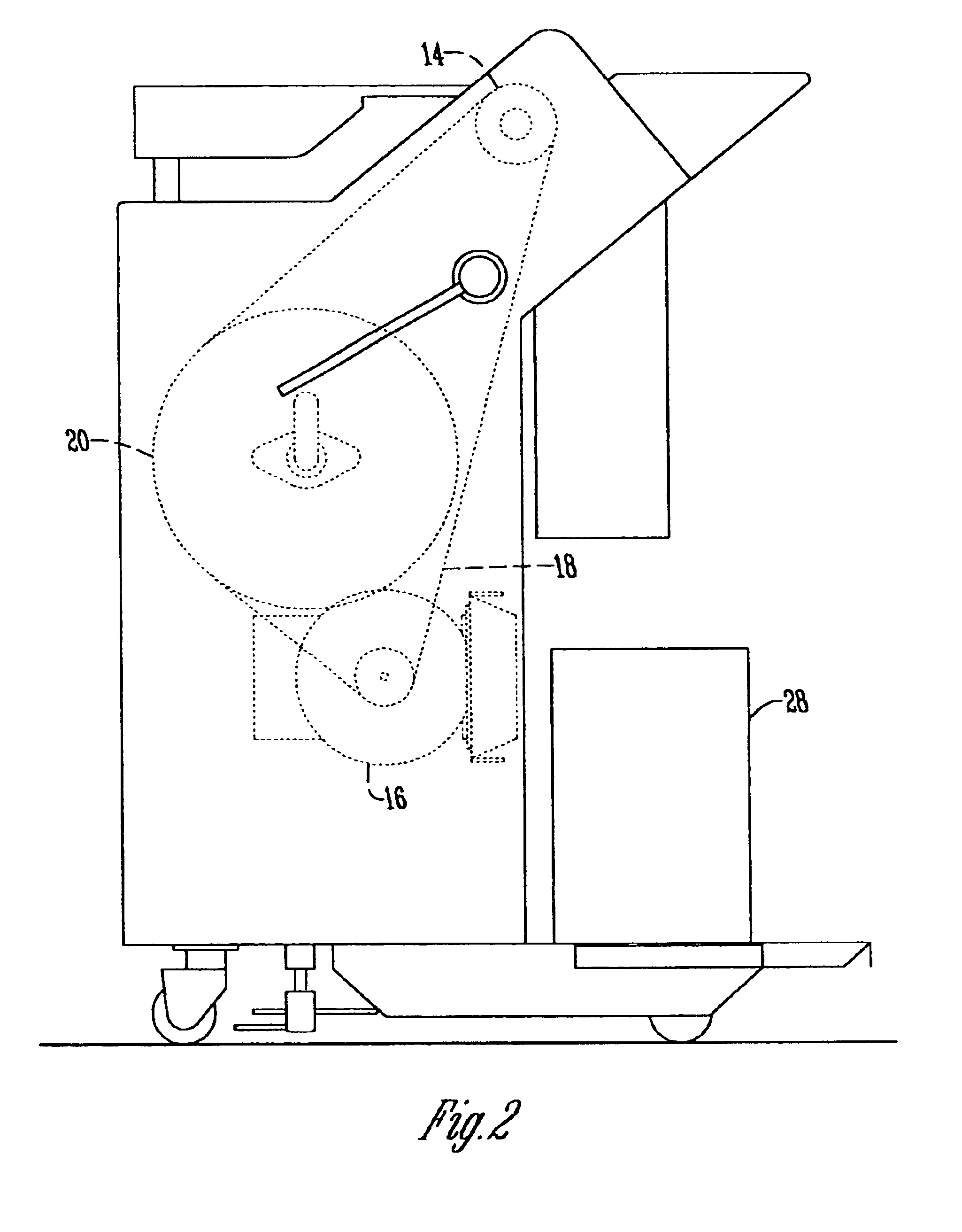
FIGS. 1-3 show a skinning machine 10 that has a frame 12 and toothroll 14 that is rotated via a power mechanism that includes a power mechanism or motor 16 by drive system 18 using pulley 20. Parallel to the top of toothroll 14 is cutting blade 22 that is mounted onto shoe 24. The machine also has a foot switch 26 operated by foot pedal 27 that controls the toothroll 14. The material removed by the skinning process on machine 10 is deposited into collection container 28.

Within the machine frame 12 are one or more sensors. In one embodiment the skinner 10 has a first sensor 30 and a second sensor 31 mounted behind the stainless steel machine frame 12 that are able to sense an identification element such as magnet 32. It should be appreciated that other identification elements include a barcode, a piece of metal, a radio frequency transmitter, an electronic tag, a key, a SRM Sensormatic device, a color or shape, or any other suitably specified device sensors 30, 31 would be able to id...


PUM


Abstract

A method and apparatus that uses safety apparel that has an identification element so that a sensor on a machine may detect the presence of the identification element. Upon detecting the presence of the identification element, the sensors electronically activate a series of switches and relays that allow the machine to operate. A plurality of relays can be set up so that when certain operational parameters occur, or do not occur, the machine is shut down. This includes a timing circuit to ensure the machine is being properly operated. Once the machine shuts down the operator must repeat the procedure of placing the identification element in communication with the sensors.

Description

BACKGROUND OF THE INVENTIONProtective apparel such as gloves are regularly worn by machine operators to make the operation of some machines safer. Gloves for example have been designed in order to prevent one's hands from being cut by a cutting blade. Prior art discloses several types of mechanisms that attempt to prevent or minimize the possibility of operators being injured when working with machines. These devices require the use of mechanisms, special mats, shoes, or other equipment that is cumbersome, expensive and unreliable. These safety devices give a false sense of security to the operator and can add additional hazards to the machine. Furthermore, prior art has mainly focused on safety devices that only protect the machine operator and not third parties.It is therefore desired to provide a system that will ensure that a machine will not operate unless the apparel is properly worn. As a result, operators of the machine will be forced to properly wear their apparel and unpro...

Claims


Application Information

Patent Timeline
IPC IPC(8): A22B5/16A22B5/00A22C17/12A22C17/00F16P3/14F16P3/00
CPCA22B5/166A22C17/12F16P3/145F16P3/147F16P3/14
Inventor BRUINSMA, THEO R.JOYNT, PAUL J.BERGMAN, MATTHEW
Owner STORK TOWNSEND BV
Why Eureka
Try Eureka