Water bed structure

a technology for water beds and water beds, applied in the direction of beds, fluid mattresses, couches, etc., can solve the problems of shortening the use life of water beds, reducing the esthetical value of an overall appearance increasing the material cost to lower etc., to achieve the effect of reducing material costs, preventing the dilating of air protection borders, and elevating the practicability of the water beds

Inactive Publication Date: 2005-02-22
CHOW ANDY S
View PDF41 Cites 17 Cited by
  • Summary
  • Abstract
  • Description
  • Claims
  • Application Information

AI Technical Summary

Benefits of technology

The primary object of the invention is to provide a water bed structure having a concave bed body, air protection borders and a bed housing as separate parts thereof. When wear occurs after long-term usage, any of the aforesaid three parts can be individually replaced instead having to replace an integral structure made of the three aforesaid parts, thereby reducing material costs for elevating practicability of the water bed.
The secondary object of the invention is to provide a water bed structure having a bed housing in an inverted U-shape design. Using the inverted U-shape design, openings of the concave bed body and air inlet plugs of the air protection borders are concealed to beautify an overall appearance of the water bed, preventing the air protection borders from dilating, and lengthening usage lifespan of the water bed as well as completely eliminating a drawback of water leakage.
The other object of the invention is to provide a water bed structure having adhesive tapes or zippers at a periphery of the concave body or the bed housing thereof. Using the adhesive tapes or zippers, various sanitary and health mattresses can be additionally installed to optimize effects and economical values of the water bed.
To accomplish the aforesaid objects, a water bed structure according to the invention comprises water containing bodies, a concave bed body, air protection borders and a bed housing. The concave bed body has each of four sides thereof provided with at least two openings for installing four unfilled air protection borders through the openings. At appropriate positions, the four air protection borders are also provided with air inlet plugs that are exactly located at the openings at the four sides of the four air protection borders. The four air protection border form a large accommodating space when assembled. The accommodating space has a middle part thereof disposed with a longitudinal central air bag or a long sponge, such that two water containing body accommodating chambers are formed. Within each of two outer layers is a plurality of parallel transverse pull strip spacers that are loop-like and hollow structures. At appropriate positions, two ends of the longitudinal central air bag or the long sponge are provided with adhesive tapes attached to head and foot ends of the accommodating chambers. The bed housing is devised in an inverted U-shape. The assembled air protection borders and the concave bed of the water containing beds are placed into the bed housing in an upward direction, such that the openings of the concave bed body and the air inlet plugs of the air protection borders are concealed, thereby beautifying an overall appearance of the water bed, preventing the air protection borders from dilating, and lengthening usage lifespan of the water bed as well as completely eliminating a drawback of water leakage.

Problems solved by technology

Thus, material costs are increased to lower practicability of the water bed.2. When the water bed structure is in assembly, the openings of the bed housing and the air inlet plugs of the air protection borders are exposed, such that esthetical values of an overall appearance of the water bed are reduced.3. After a certain period of usage of the prior water bed structure, the air protection borders are likely to dilate to further shorten usage lifespan of the water bed.4. The prior water bed structure lacks additional sanitary mattresses, thereby again lowering effects and economical values of the water bed.

Method used


Image

  • Water bed structure
  • Water bed structure
  • Water bed structure

Examples


Embodiment Construction

To better understand effects, structures and characteristics of the invention, detailed descriptions of preferred embodiments shall be given with the accompanying drawings below.

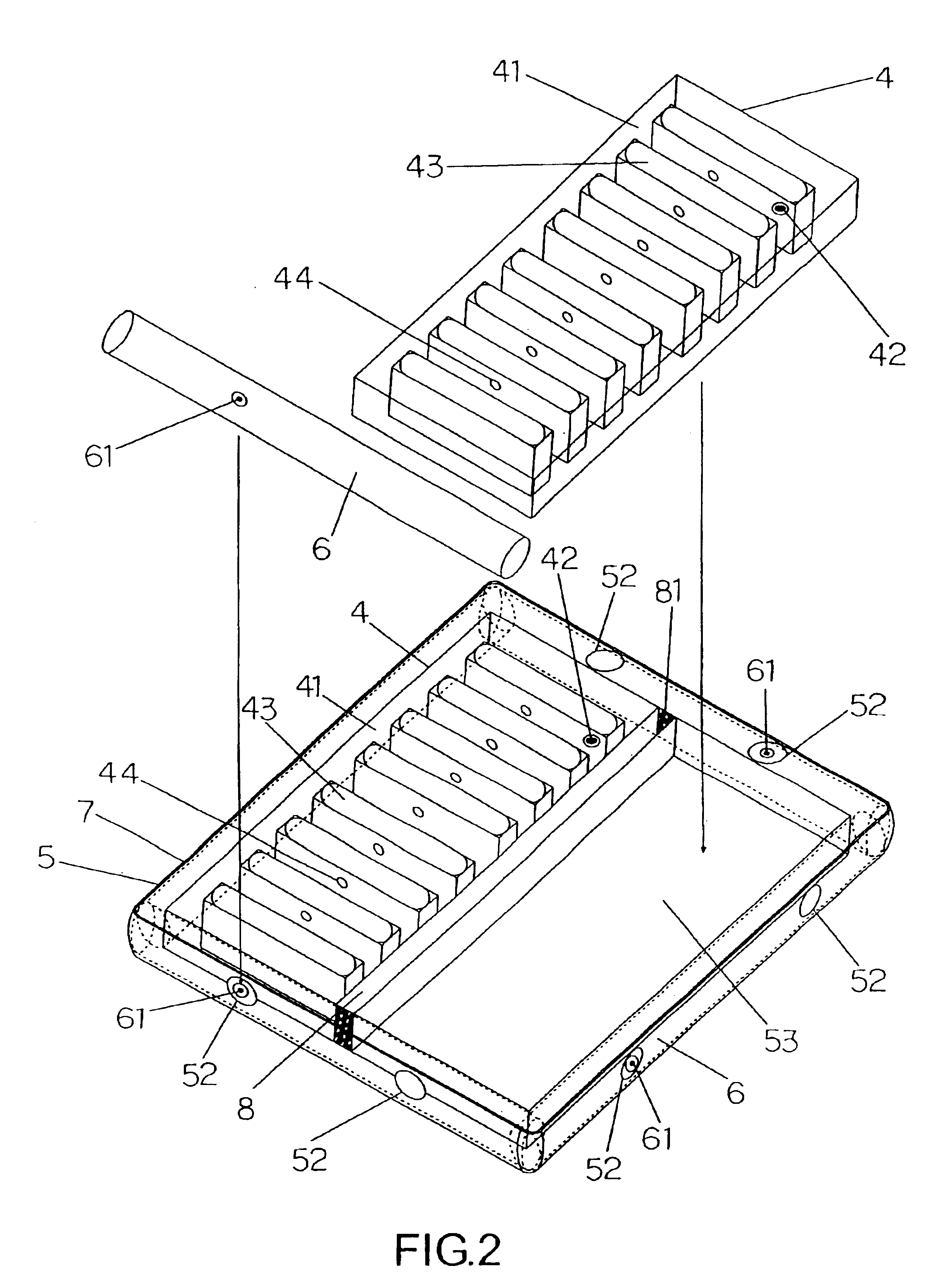
Referring to FIG. 2 showing an exploded elevational schematic view illustrating a dual-part double-bed according to the invention, the invention comprises two water containing bodies 4, a concave bed body 5, air protection borders 6 and a bed housing 7.

The concave bed body 5 has each side thereof provided with at least two openings 52 for installing four unfilled air protection borders 6 through the openings 52, thereby forming a large accommodating space 51. The accommodating space 51 has a middle part thereof disposed with a longitudinal central air bag or a long sponge 8, such that two water containing body accommodating chambers 53 are formed for placing the two water containing bodies 4. At appropriate positions, two ends of the central air bag or the long sponge are provided with adhesive tapes attache...


PUM


Abstract

A water bed structure includes water containing bodies, a concave bed body, air protection borders and a bed housing, wherein the water containing bodies are installed in accommodating chambers formed by the concave bed body and the air protection borders, and are placed into the bed housing. The concave bed body has each of four sides thereof provided with at least two openings for installing four unfilled air protection borders through the openings. The four air protection borders are provided with air inlet plugs that are located at the openings at the four sides of the four air protection borders. The assembled air protection borders and the concave bed of the water containing beds are placed into an inverted U-shape bed housing in an upward direction, such that the openings of the concave bed body and the air inlet plugs of the air protection borders are concealed.

Description

BACKGROUND OF THE INVENTION(a) Field of the InventionThe invention relates to a water bed structure, and more particularly, to a water bed structure, which is capable of lowering costs of replacement materials when replaceable materials thereof are worn, beatifying appearance of the overall water bed structure, completely eliminating a drawback of water leakage, and lengthening lifespan as well as easily controlling elasticity for softness and hardness, thereby optimizing practicability thereof.(b) Description of the Prior ArtReferring to FIG. 1 showing an elevational schematic view of a prior double-bed, the prior water bed structure comprises left and right water-containing bodies 1 and bed housing 2. Each of the water containing bodies 1 has an outer layer 11; a water inlet plug 12 at an appropriate position of each outer layer 11; a plurality of equidistant and parallel transverse pull strip spacers 13 that are loop-like and hollow structures; and a water opening 14 disposed at ...

Claims


Application Information

Patent Timeline
Patent Type & Authority Patents(United States)
IPC IPC(8): A47C27/10A47C27/08
CPCA47C27/085A47C27/081
Inventor CHOW, ANDY S.
Owner CHOW ANDY S
Why Eureka
Try Eureka