
Structure of an engine starter of a remote-controlled car

a technology for remote-controlled cars and starters, which is applied in the direction of engine starters, muscle-operated starters, inter-engaging clutches, etc., can solve the problems of one-way clutch sleeves that are susceptible to high temperature, the car engine to build up its revolutional speed, and the one-way clutch sleeves to yield by a high temperature. , to achieve the effect of eliminating the shortcomings inherent in the conventional starter structur

Inactive Publication Date: 2005-02-22
YEH CHIH WEI
View PDF11 Cites 6 Cited by
  • Summary
  • Abstract
  • Description
  • Claims
  • Application Information

AI Technical Summary

Benefits of technology

Accordingly, it is the object of the present invention to provide a starter (driver) for a remote control miniaturized model car capable of eliminating the aforementioned shortcomings inherent to the conventional starter structure.
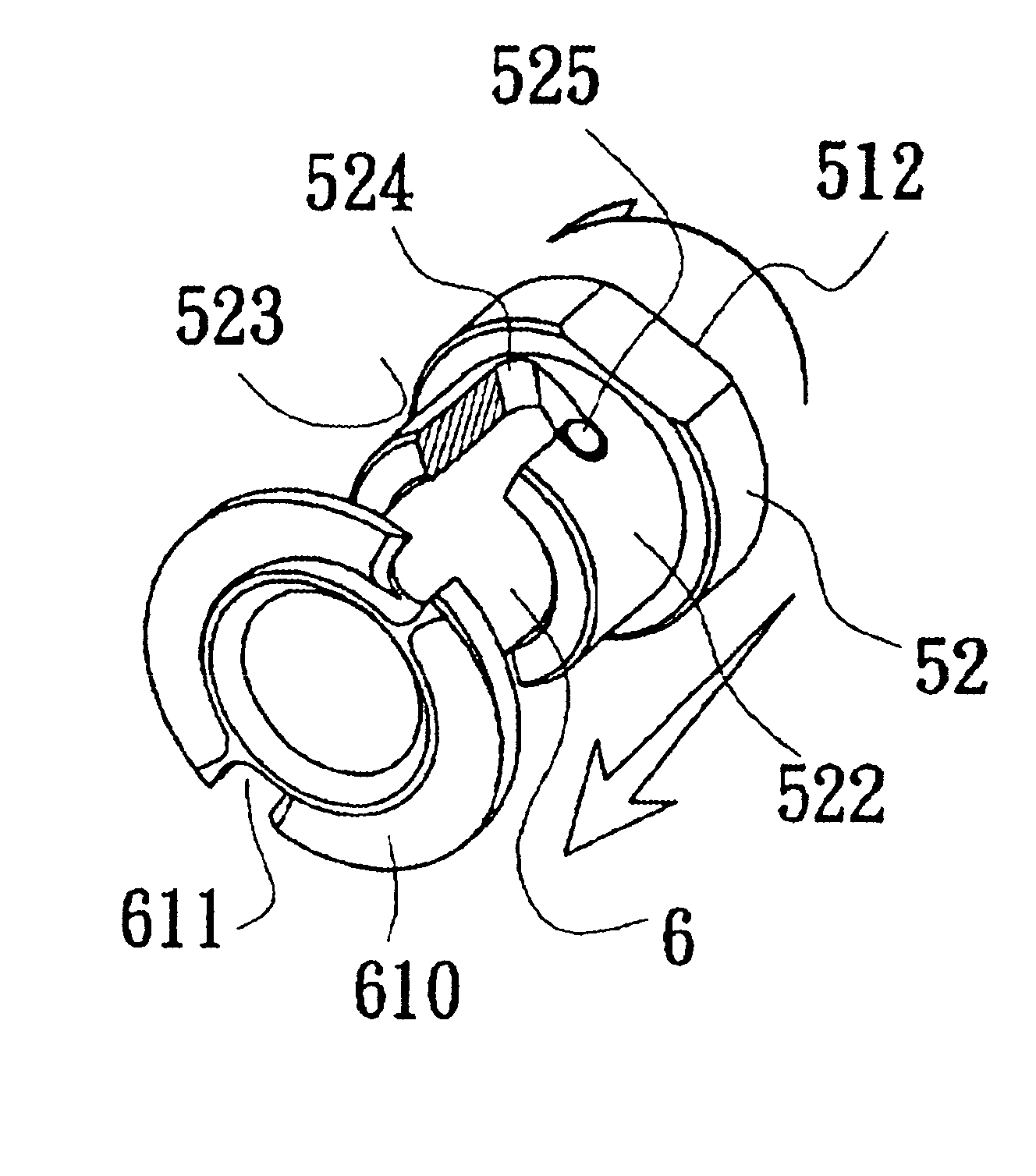
In the present invention, to enable the one way clutch sleeve to perform perfect separation from the starter shaft as soon as the car engine has attained its normal speed, the coupled part of the starter shaft with the rear engine shaft is formed into a slanted surface with chamfered edges so as to smoothen the slide movement between the two shafts thereby preventing extra mechanical power loss and early yielding of the clutch sleeve. Furthermore, a steel ball provided at the end terminal of the starter shaft serves to fix the starter shaft at a relevant retrieval position after its separation from the rear engine shaft so as to prevent excursion of the starter shaft due to vibration of the car engine.

Problems solved by technology

Meanwhile, the aforementioned conventional starter (driver) structure for initiating the miniaturized model car engine has several noticeable disadvantages, namely:1. In the time when the car engine is initiated but the rear engine shaft has not yet released from meshing with the starter shaft, the starter shaft itself together with the rear cover and the nipple chuck become loads to the car engine resulting in an obstacle for the car engine to build up its revolutional speed in a short time.2. The one way clutch sleeve encircling the starter shaft is impossible to perform perfect separation from the engine shaft when the car engine has reached its normal speed, but instead, slightly in touch with the starter shaft causing extra mechanical power loss.3. The phenomenon mentioned above further causes the one-way clutch sleeve to yield by a high temperature arising from friction.

Method used


Image

  • Structure of an engine starter of a remote-controlled car
  • Structure of an engine starter of a remote-controlled car
  • Structure of an engine starter of a remote-controlled car

Examples


Embodiment Construction

Referring to FIG. 2, the component parts of the present invention comprise a starter which is further classified into a manual pull type and a motor operated type, but now a starting motor 3 of the latter will now be described accompanying with FIG. 3, the other components are a transmission mechanism 4, a rear cover 5, and a starter shaft 6 to couple with a rear engine shaft 7.

Output power of the starting motor 3 is transmitted by the transmission mechanism 4 having a gear set inside and being connected to the rear cover at its output side. The other end of the rear cover 5 is conjoined with a sleeve 51, which has a slip bushing 52 inside. As shown in FIGS. 2 and 5, one end of the slip bushing 52 is formed into a collar 521, while the other end thereof is formed into a sleeve 522. A longitudinal slanted groove 523 having recesses 524 provided at its both ends is formed on the outer surface of slip bushing 52.

Referring to FIGS. 3 and 4, when the starter shaft 6 is inserted into the ...


PUM


Abstract

A structure for a starter (driver) of a miniaturized remote control model car engine is able to perform perfect separation of the starter shaft from the engine as soon as the engine has built up its normal speed with the aid of the slanted surface and chamfered edges formed on its coupling plate, and the retrieved starter shaft never forwardly excurses to recontact the engine shaft by a steel ball positioning device. With this structure, the extra mechanical loss and damage to the mechanical parts can be prevented in model car engines operated at an extra high speed.

Description

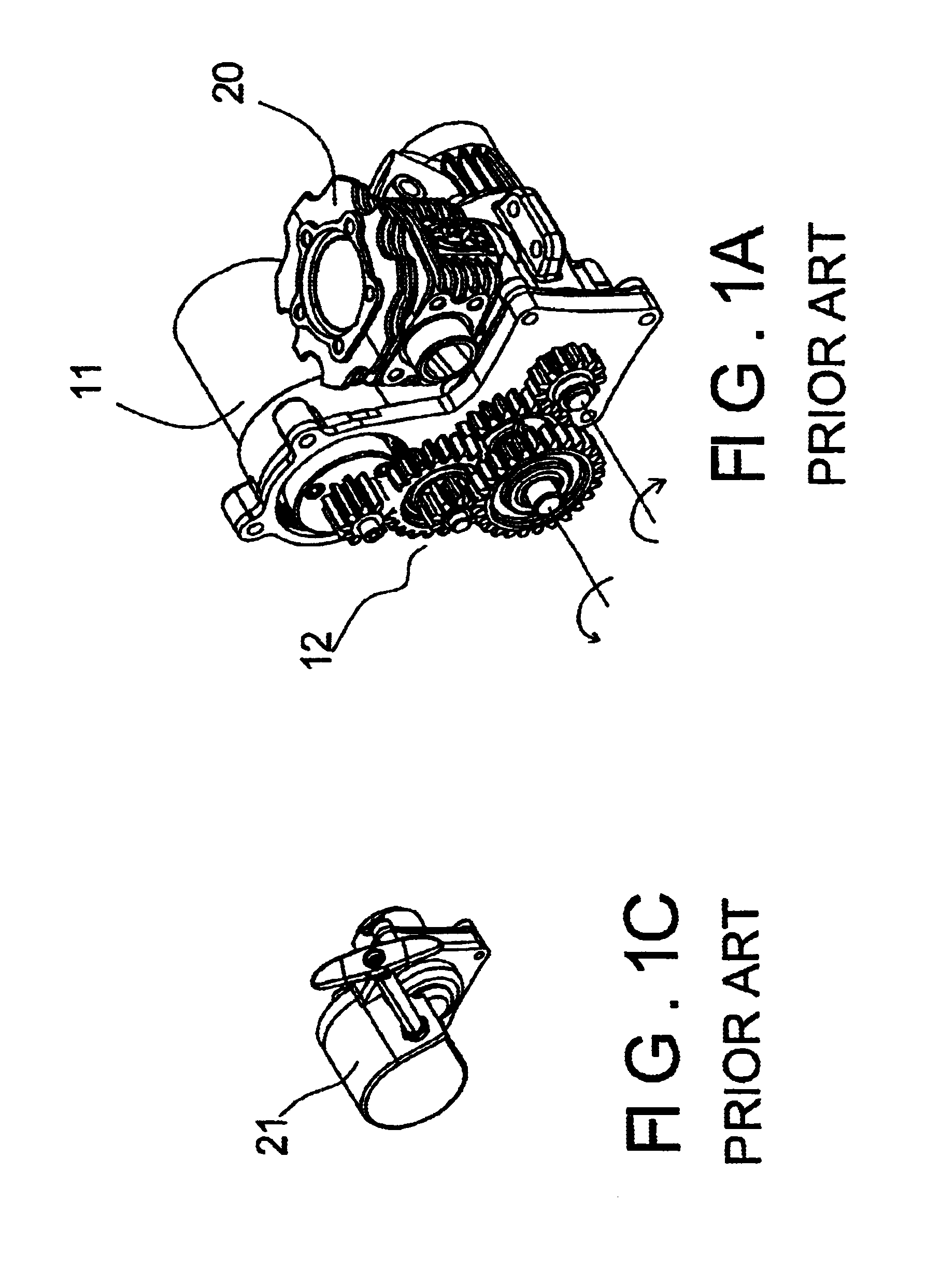
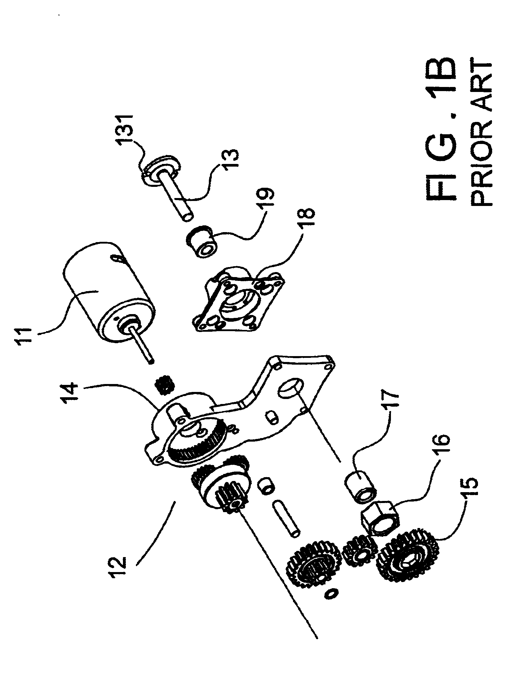
BACKGROUND OF THE INVENTION1. Field of the InventionThe present invention relates to an improved structure for a driver of a remote-controlled car, and in particular, to an improved engine starter for a remote control miniature model car capable of saving mechanical power loss and avoiding abrasion to the component parts of the structure.2. Description of the Prior ArtTo play a remote control miniaturized model car is a popular hobby nowadays. Present precise engineering techniques have realized producing a miniaturized model car with sophisticated components, which function fantastically as if those were of a real car.The conventional well-known remote control miniaturized model car requires a starter (driver) to initiate its engine. There are generally two types of starter available, a manual pull type and a motor starting type. The principle of favorably used motor starting type will be illustrated accompanying with FIGS. 1A, 1B hereinbelow.As shown in FIGS. 1A and 1B, the motor ...

Claims


Application Information

Patent Timeline
Patent Type & Authority Patents(United States)
IPC IPC(8): F02N15/02F02N3/02F02N3/00
CPCF02N15/021F02D2400/06F02N3/02Y10T74/134Y10T74/13
Inventor YEH, CHIH-WEI
Owner YEH CHIH WEI
Learn More