Cooling system for internal combustion engine

a technology for internal combustion engines and cooling systems, applied in engine cooling apparatus, engine controllers, electric control, etc., can solve the problems of power loss, poor response of cooling systems, and inability to control the coolant temperature to the target coolant temperature, so as to improve fuel efficiency and output performance. the effect of improving the respons

Inactive Publication Date: 2005-02-22
TOYOTA JIDOSHA KK
View PDF7 Cites 25 Cited by
  • Summary
  • Abstract
  • Description
  • Claims
  • Application Information

AI Technical Summary

Benefits of technology

It is therefore an object of the invention to provide a cooling system for an internal combustion engine, in which the coolant temperature of the internal combustion engine can be controlled to the target coolant temperature with improved response, even if the coolant loss changes with a change in the operating state of the internal combustion engine.
Accordingly, even if the cooling loss (i.e., the quantity of heat equivalent to the cooling loss) changes with a change in the operating state of the engine, the actuator is controlled in accordance with the change of the cooling loss. Therefore, the coolant temperature of the engine can be controlled to the target coolant temperature with good response.
Accordingly, the coolant temperature is smoothly controlled to the target coolant temperature at an increased speed with improved accuracy, even when the quantity of heat received or radiated in the heat receiving / radiating circuit(s) changes. Namely, the degree of overshoot or undershoot in the coolant temperature control can be reduced, and therefore the target coolant temperature need not be lowered in view of the heat resistance of components that constitute the internal combustion engine. In this specification, the overshoot means a phenomenon where the coolant temperature exceeds the target coolant temperature after reaching the target level, and the undershoot means a phenomenon where the coolant temperature falls below the target cooling temperature after being lowered down to the target level. Since the target cooling temperature need not be lowered as described above, it is possible to avoid or suppress friction increases in the engine and automatic transmission due to the otherwise possible reduction of the target cooling temperature, and thereby avoid or suppress deterioration of the fuel efficiency (i.e., an increase of the fuel consumption).
The cooling loss is supposed to vary with a change in the quantity of heat radiated from the main body of the internal combustion engine (which quantity will be called “engine body radiated heat quantity”), as well as a change in the operating state of the internal combustion engine. According to this embodiment, therefore, the engine body radiated heat quantity is calculated, and the calculated heat quantity is reflected in the calculation of the radiator flow rate. Accordingly, even if the engine body radiated heat quantity changes, the coolant temperature is more smoothly and accurately controlled to the target coolant temperature. Namely, the degree of overshoot or undershoot in the coolant temperature control can be reduced, and therefore the target coolant temperature need not be lowered in view of the heat resistance of components that constitute the internal combustion engine. This arrangement makes it possible to avoid or suppress friction increases in the engine and automatic transmission due to the otherwise possible reduction of the target cooling temperature, and thereby avoid or suppress deterioration of the fuel efficiency (i.e., an increase of the fuel consumption).

Problems solved by technology

Therefore, the cooling system suffers from poor response when controlling the coolant temperature to the target coolant temperature.
In particular, when a quantity of heat equivalent to a cooling loss of the engine changes with a change in the operating state of the engine, the coolant temperature cannot be controlled to the target coolant temperature with good response.
If the coolant loss changes as described above, a power loss takes place which is detrimental to improvements in the fuel efficiency and the output performance.
A similar problem may be encountered in a cooling system in which the flow rate of coolant passing through a radiator is controlled by an electric water pump, in place of the flow control valve.

Method used


Image

  • Cooling system for internal combustion engine
  • Cooling system for internal combustion engine
  • Cooling system for internal combustion engine

Examples


first embodiment

A first embodiment of the invention will be described in detail with reference to FIG. 1 through FIG. 4.

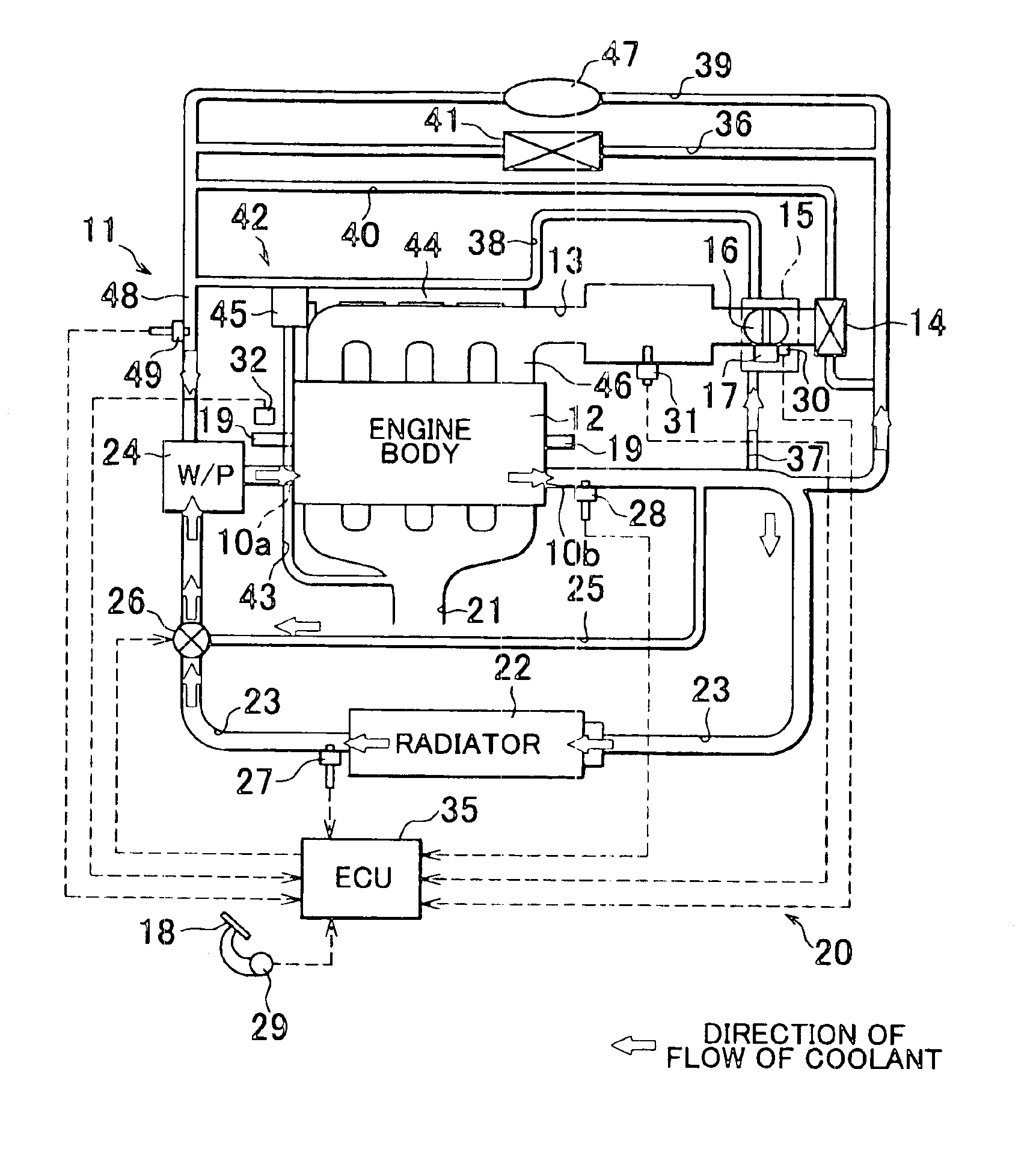
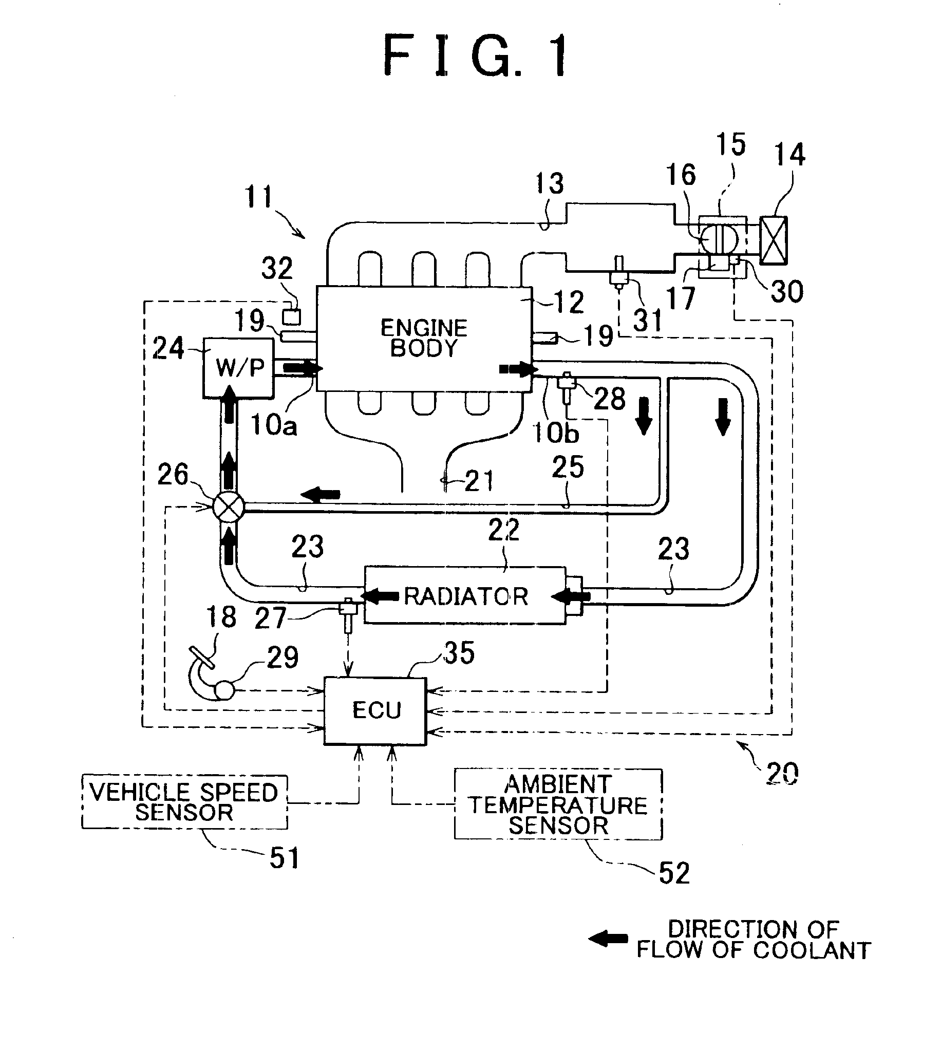
As shown in FIG. 1, a principal part of a multi-cylinder engine installed on a motor vehicle consists of an engine body 12 including a cylinder block, a cylinder head and other components. To the engine body 12 is connected an intake passage 13 through which the air is introduced into a combustion chamber of each cylinder. The intake passage 13 is provided with an air cleaner 14 and a throttle body 15. The air cleaner 14 is a filter that traps and removes dust in the air introduced into the engine body 12. A throttle valve 16 is rotatably supported in the throttle body 15, and a throttle motor 17 for driving the throttle valve 16 is operatively coupled to the throttle valve 16.

An electronic control unit (ECU) 35 controls the throttle motor 17 as described later, based on an operation of the driver to depress an accelerator pedal 18 and other parameters, so as to rotate the throttl...

second embodiment

The second embodiment as described above in detail yields the following effects in addition to the above-described effects (a) to (d).

(e) With various heat receiving / radiating circuits that bypass the radiator 22 thus provided, heat is received or radiated (in other words, incoming and outgoing radiation of heat takes place) in the process in which the coolant passes through these heat receiving / radiating circuits. The coolant which has been subjected to the incoming and outgoing radiation of heat flows into the radiator passage 23 through the water pump 24, and passes through the water jacket in the engine body 12 again. If a large quantity of heat is received or radiated in the heat receiving / radiating circuits, the engine outlet water temperature To is controlled to a target value (i.e., target engine outlet water temperature Tt) at a reduced speed with a reduced accuracy unless the received / radiated heat quantity is taken into consideration, which may result in an increased degr...

third embodiment

The third embodiment as described above in detail provides the following effects in addition to the effects (a) through (d) as described above.

(g) The cooling loss Qw of the engine body 12 is supposed to vary with the quantity of heat radiated from the engine body 12 (i.e., engine body radiated heat quantity Qoeng), in addition to the engine speed NE and the engine load. Here, the engine body radiated heat quantity Qoeng is significantly influenced by the vehicle speed SPD. Also, the engine body radiated heat quantity Qoeng is influenced by the ambient temperature THA though the degree of the influence is not so great as that of the influence by the vehicle speed SPD. If the influences of the vehicle speed SPD and the ambient temperature THA are large, the engine outlet water temperature To is slowly controlled to a target value (i.e., target engine outlet water temperature Tt) with a reduced accuracy unless the engine body radiated heat quantity Qoeng is taken into consideration, w...


PUM


Abstract

A cooling system for an internal combustion engine includes a radiator provided in a coolant circulation path of the internal combustion engine, and an actuator that controls a flow rate of a coolant that passes through the radiator. In the cooling system, the actuator is controlled so that a coolant temperature of the engine becomes substantially equal to a target coolant temperature. The cooling system calculates a cooling loss as a quantity of heat removed from the engine by the coolant, based on an operating state of the engine, and calculates a required radiator flow rate, based on the cooling loss, the target coolant temperature, and a temperature of the coolant that has passed through the radiator. The required radiator flow rate represents a quantity of the coolant required to pass through the radiator so as to achieve the target coolant temperature. The cooling system then controls the actuator based on the required radiator flow rate.

Description

INCORPORATION BY REFERENCEThe disclosure of Japanese Patent Application No. 2002-034961 filed on Feb. 13, 2002, including the specification, drawings and abstract, is incorporated herein by reference in its entirety.BACKGROUND OF THE INVENTION1. Field of the InventionThe invention relates to a cooling system adapted to cool an internal combustion engine by circulating a coolant and effecting heat exchange between the coolant and the internal combustion engine.2. Description of Related ArtA known cooling system for a water-cooled engine installed on a motor vehicle, or the like, includes a radiator provided in a coolant circulation path of the engine for cooling a coolant or cooling water, and a flow control valve that controls the flow rate of the coolant that passes through the radiator. In this type of cooling system, the temperature of the engine coolant changes in accordance with the flow rate of the coolant that is controlled through control of the opening of the flow control v...

Claims


Application Information

Patent Timeline
Patent Type & Authority Patents(United States)
IPC IPC(8): F01P7/16F01P7/14F02D45/00
CPCF01P7/167F01P2007/146F01P2023/08F01P2025/13F01P2025/66F01P2025/36F01P2025/62F01P2025/64F01P2025/32
Inventor TAKAGI, ISAOYOSHIKAWA, SHIGETAKASHINPO, YOSHIKAZU
Owner TOYOTA JIDOSHA KK
Why Eureka
Try Eureka