Thermally powered VAV diffuser and control assembly

a vav diffuser and control assembly technology, which is applied in the direction of ventilation systems, heating types, instruments, etc., can solve the problems of difficult maintenance and/or replacement of the sensor-actuator and linkage components in the neck of the diffuser, and the vav diffuser of u.s. pat. no. 4,509,678 is not capable of variable air volume (vav) discharge in both heating and cooling modes

Inactive Publication Date: 2005-02-22
ACUTHERM
View PDF12 Cites 15 Cited by
  • Summary
  • Abstract
  • Description
  • Claims
  • Application Information

AI Technical Summary

Benefits of technology

The lever can be spring biased to a normally closed position or gravity biased to a normally open position, and most preferably the linkage assembly includes a change over linkage that moves the damper member to the closed position each time the diffuser changes over between heating and cooling modes. A balancing arm also may be provided which allows the damper to be dropped to a fully open position, permitting system balancing, without having to remove the diffuser appearance panel.

Problems solved by technology

This makes maintenance and / or replacement of the sensor-actuator and linkage components in the neck of the diffuser more difficult.
The VAV diffuser of U.S. Pat. No. 4,509,678 also is not capable of variable air volume (VAV) discharge in both heating and cooling modes.

Method used


Image

  • Thermally powered VAV diffuser and control assembly
  • Thermally powered VAV diffuser and control assembly
  • Thermally powered VAV diffuser and control assembly

Examples


second embodiment

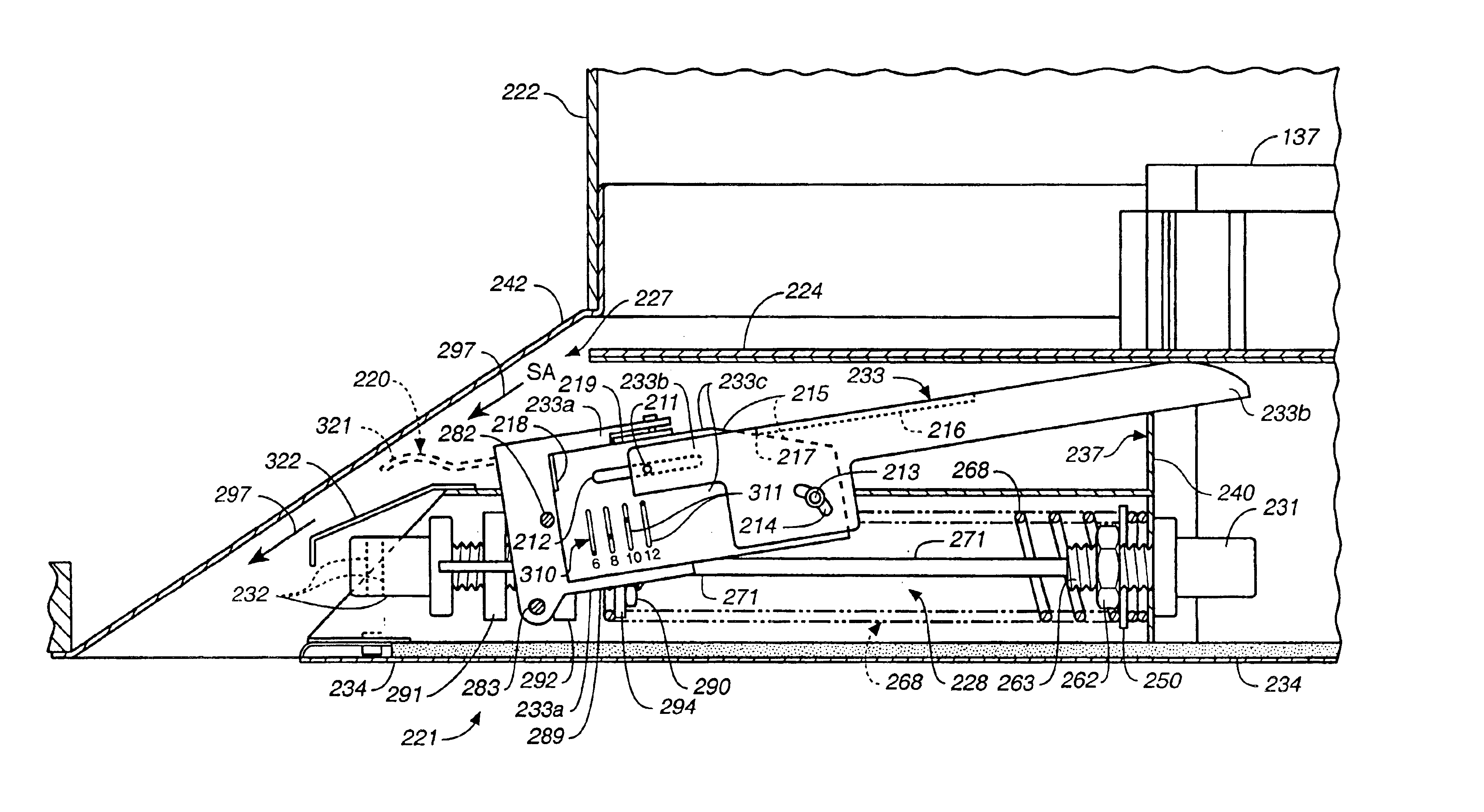
Turning now to the alternative embodiment of the diffuser of the present invention as shown in FIGS. 9-12, a diffuser 221 is provided which is constructed in a manner similar to that of diffuser 21, except that a somewhat different control assembly 228 is provided.

Supply air flow tube 237 again has a supply air sensor-actuator 231 mounted in it. Sensor-actuator 231, however, is fixedly mounted to tube wall 240 so that the body of sensor-actuator 231 does not move. Piston 271 of supply air or change-over sensor-actuator 231, however, does move to the left in FIG. 9 relative to wall 240 when warm air is in tube 237 and moves to the right when cool air is present in supply air flow tube 237.

A tension (only) spring 268 is coupled at one end by plate or washer 250 and nut 262 on the end 263 of sensor-actuator 231. The opposite end of tension spring 268 is coupled by a spring gripping member 294 having four fingers 295 which are positioned in pairs of fingers on either side of piston 271 ...


PUM


Abstract

A thermally powered VAV diffuser assembly (21, 221) having a housing (42, 242) formed for coupling to a supply air duct or conduit (22, 222), a damper (24, 224) mounted across a supply air opening (27, 227) for movement relative thereto to vary the volume of supply air discharge from the diffuser and a thermally powered damper position controlled device or assembly (28, 228). The control assembly (28, 228) includes not more than two sensor-actuators (31, 32, 231, 232) and a movable linkage assembly. The linkage assembly transmits movement of the sensor-actuators (31, 32, 231, 232) to the damper (24, 224) for displacement of the damper (24, 224) to vary the volume discharged and to produce change-overs between heating and cooling modes. The heating mode and cooling mode set point temperatures are each independently adjustable, and the movable linkage assembly includes a lever (33, 233) pivoted about two pivot points by axles (82, 83, 282, 283) which slide in slots (87, 88, 287, 288). The sensor-actuators (31, 32, 231, 232) and all of the movable linkage assembly are located on a room side of the movable damper (24, 224) so that removal of the appearance panel (34, 234) exposes these elements for ease of maintenance, repair and replacement. An adjustable minimum flow stop (233a, 233b, 233c) balancing arm (220) and change-over linkage (275) also are provided.

Description

TECHNICAL FIELDThe present invention relates, in general, to thermally powered VAV diffusers of the type used in heating, ventilating and air conditioning (HVAC) systems, and more particularly, relates to systems employing a thermally powered sensor-actuator to move the damper or blade assembly of an air diffuser to vary the volume of air discharged from the diffuser.BACKGROUND ARTThermally powered air diffusers have been widely employed in HVAC systems. The control assembly for such VAV diffusers typically employs a plurality of thermal sensor-actuators and a damper displacing linkage assembly. The sensor-actuators each have a contained wax that expands and contracts with temperature changes and drives a piston. The piston, in turn, is used to displace the linkage assembly that controls the position of the diffuser damper, baffle, disk or blade assembly. Thermally powered VAV diffuser assemblies, for example, are shown in U.S. Pat. No. Re30,953, U.S. Pat. Nos. 4,491,270, 4,509,678,...

Claims


Application Information

Patent Timeline
Patent Type & Authority Patents(United States)
IPC IPC(8): F24F11/04F24F11/053F24F3/044F24F11/76
CPCF24F11/053F24F3/0442F24F11/76
Inventor HUNKA, ROBERT S.
Owner ACUTHERM
Why Eureka
Try Eureka