Plug-in type liquid atomizer

a liquid atomizer and plug-in technology, which is applied in the direction of sound producing devices, movable spraying devices, instruments, etc., can solve the problems of complex atomizers, high cost, and limited driving voltage, and achieve the effect of rapid ra

a liquid atomizer and plug-in technology, which is applied in the direction of sound producing devices, movable spraying devices, instruments, etc., can solve the problems of complex atomizers, high cost, and limited driving voltage, and achieve the effect of rapid ra

US6857580B2Inactive Publication Date: 2005-02-22SC JOHNSON & SON INC

Image

  • Plug-in type liquid atomizer
  • Plug-in type liquid atomizer
  • Plug-in type liquid atomizer

Examples


Embodiment Construction

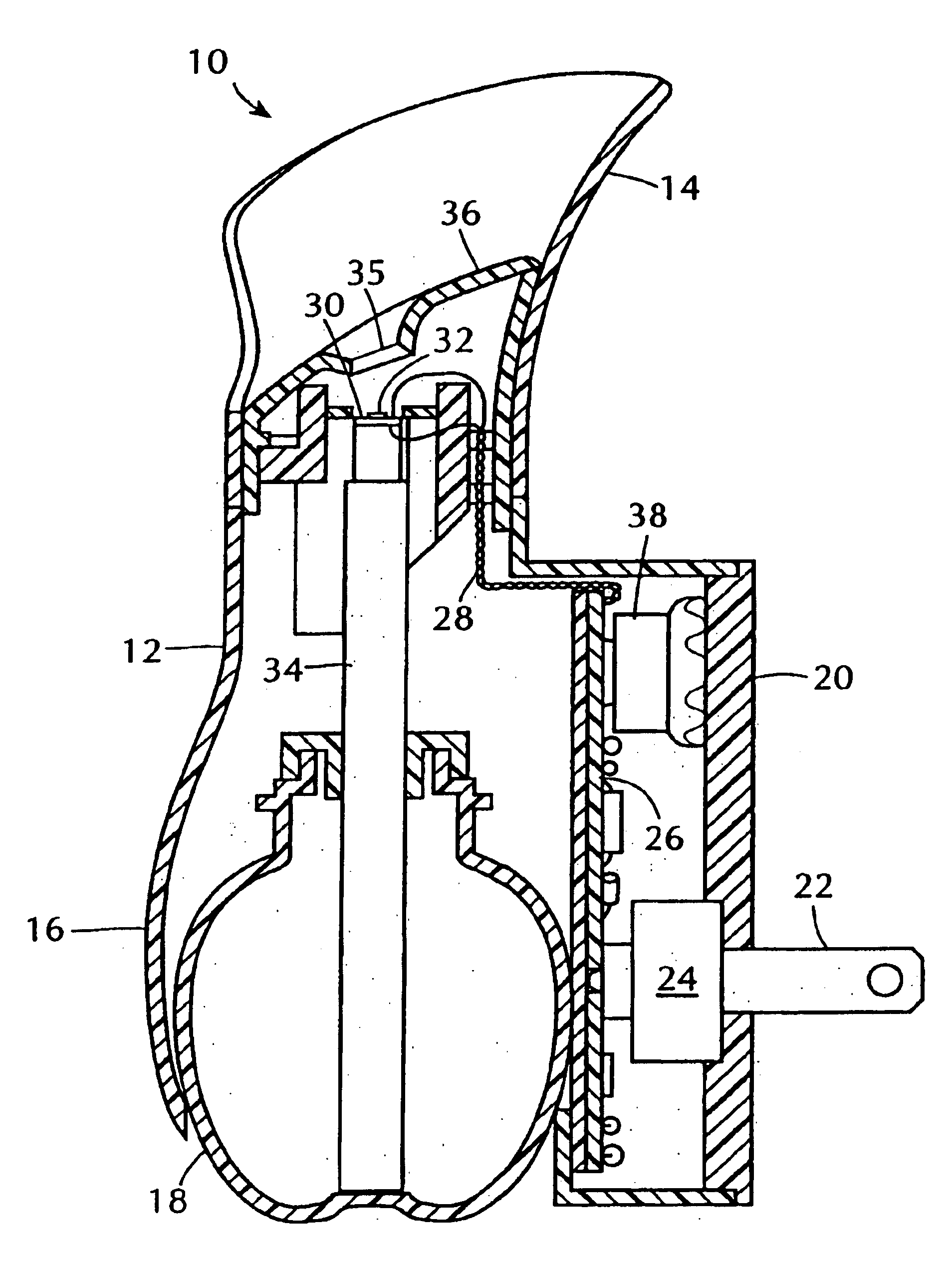
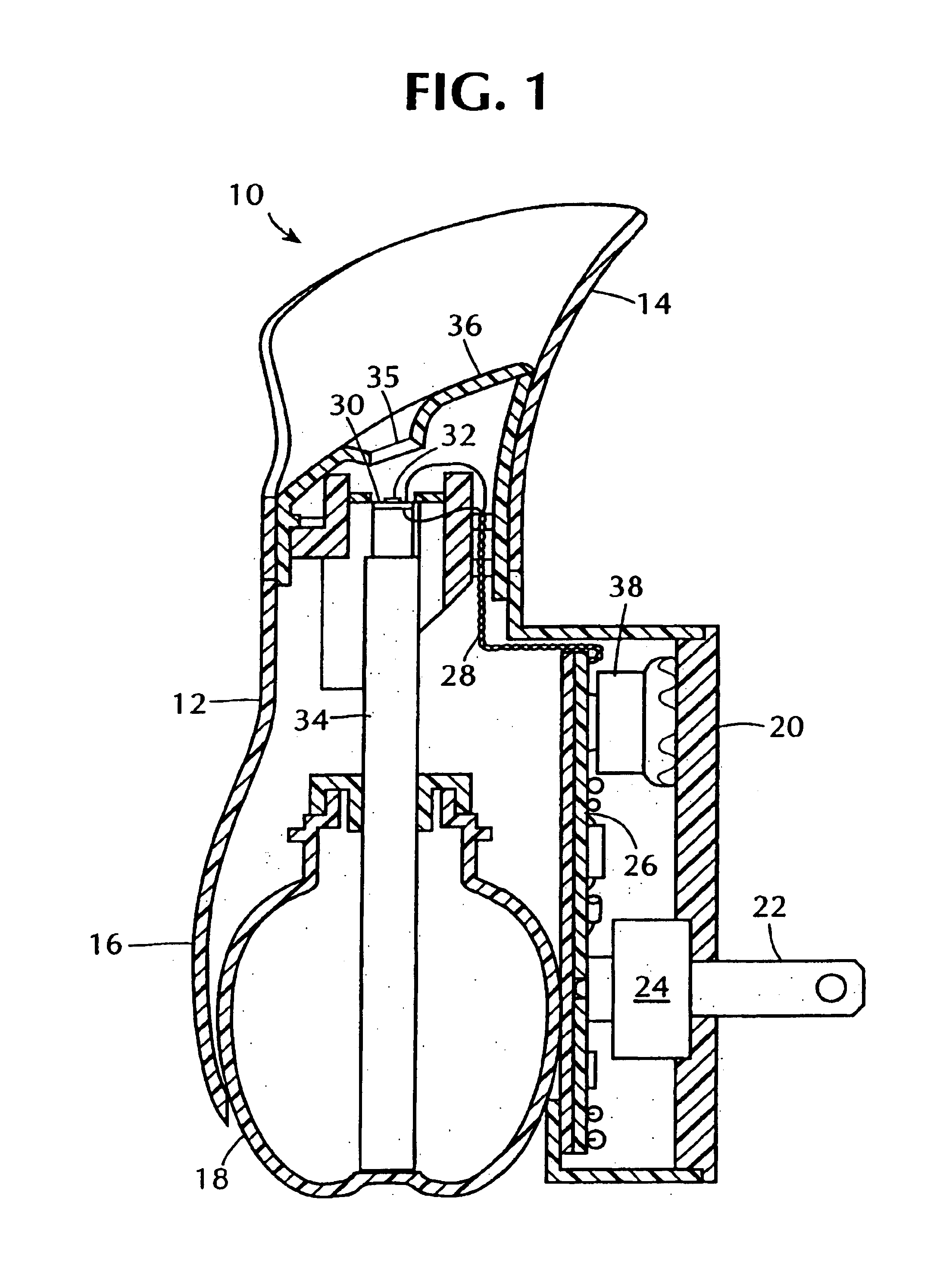
An atomizing device 10, according to one embodiment of the present invention, comprises a hollow plastic housing 12 formed with an outwardly flaring top region 14 for expelling atomized liquid droplets, a bulbous open lower region 16 for removably receiving a removable reservoir 18 which contains a liquid to be atomized, and an expansive opening at one side which supports a flat vertical wall 20.

The wall 20 supports a pair of electrical prongs 22 (only one of which can be seen in FIG. 1) for plugging into an ordinary electrical wall outlet. The prongs 22 are supported in a solid mounting piece 24 which is fixed into the wall 20, so that when the atomizing device 10 is plugged into an electrical wall outlet, it is firmly supported by the outlet and requires no other support. The prongs 22 shown in FIG. 1 are configured for conventional North American electrical outlets. For use of the device in other countries, the prongs would be configured and positioned to fit in outlets used in t...


PUM


Abstract

A piezoelectrically actuated liquid atomizer device which applies alternating voltages from an ordinary wall outlet to a piezoelectric actuator intermittently and at a high rate sufficient to cause an atomization plate which is vibrated by the actuator to form small droplets from liquid which is supplied to the plate. The intermittent application of voltages to the piezoelectric actuator is carried out according to a duty cycle in which the off times are adjustable. An override of the duty cycle is provided so that the piezoelectric actuator operates continuously for intervals which are manually or automatically controlled.

Description

BACKGROUND OF THE INVENTION1. Field of the InventionThis invention relates to liquid atomizing devices such as misters and dispersants for fragrances, air fresheners and insecticides.2. Description of the Related ArtIt is known to atomize liquids which contain air fresheners, fragrances and insecticides by suppling the liquid to a plate which is vibrated at high frequency by a piezoelectric actuator. Battery powered atomizer devices for dispensing air fresheners and insecticides are shown for example, in U.S. Pat. No. 5,657,926 and No. 6,085,740 and in U.S. application Ser. No. 09 / 519,560, filed Mar. 6, 2000. It has also been proposed in U.S. Pat. No. 5,803,362, to power a piezoelectric actuated atomizer with an alternating current supply.Battery powered atomizers are subject to the amount of energy available in the battery; and they are limited in the magnitude of driving voltage that can be applied to the piezoelectric actuator. While an alternating current driven atomizer is not ...

Claims


Application Information

Patent Timeline
22 Feb 2005
Publication
US6857580B2
IPC
B05B17/04; B05B17/06; G10K9/122; G10K9/00
CPC
B05B17/0607; G10K9/122; B05B17/0646; B05B17/04; B05B17/06
Inventors
WALTER, SCOTT D.; HELF, THOMAS A.