Lighting apparatus with enhanced capability of heat dissipation

a technology of heat dissipation board and light source, which is applied in the direction of lighting and heating apparatus, lighting support devices, fixed installations, etc., can solve the problems of reducing the luminous efficacy, reducing the life of leds, and reducing the efficiency of light dissipation, so as to achieve the effect of conducting to and efficiently dissipating the heat board

Inactive Publication Date: 2005-02-22
PANASONIC CORP
View PDF16 Cites 158 Cited by
  • Summary
  • Abstract
  • Description
  • Claims
  • Application Information

AI Technical Summary

Benefits of technology

With this arrangement, the heat from the light emitting elements is dissipated by the heat dissipating member. Especially, since the heat dissipation board is attached at the back of the positioning areas of the LEDs, the heat from the light emitting elements can be conducted to the heat dissipation board very efficiently.
Furthermore,

Problems solved by technology

One of the problems is that when a flexible substrate is bent, the areas of the substrate where LEDs are soldered onto also bends, and then, as a result, the solder that electrically and mechanically connects LEDs with the substrate may come off.
Since the lighting apparatus of the prior art does not have a system to dissipate the heat from the LEDs, a large amount of heat liberated from the LEDs th

Method used


Image

  • Lighting apparatus with enhanced capability of heat dissipation
  • Lighting apparatus with enhanced capability of heat dissipation
  • Lighting apparatus with enhanced capability of heat dissipation

Examples


first embodiment

1. Structure of the Lighting Apparatus

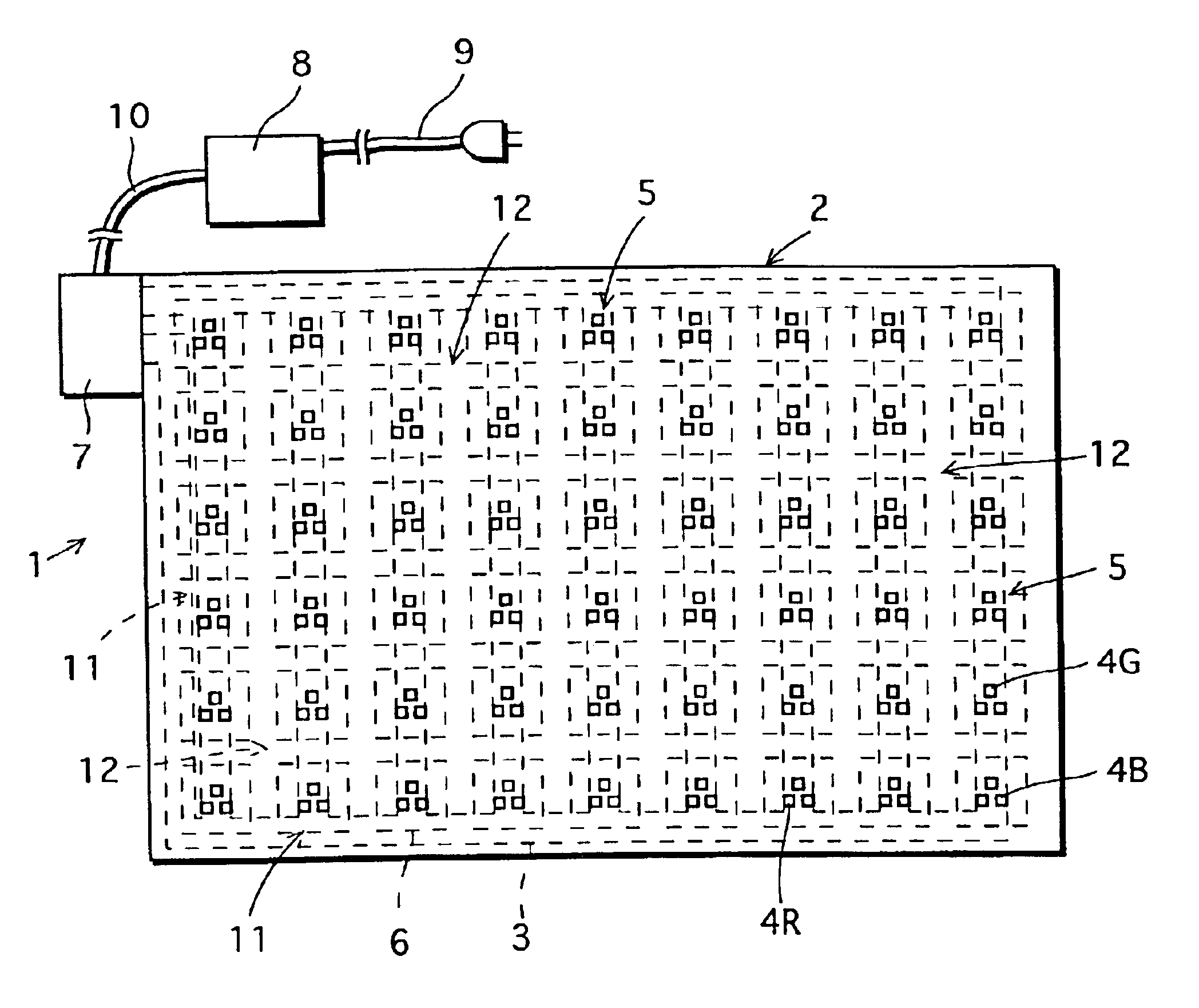
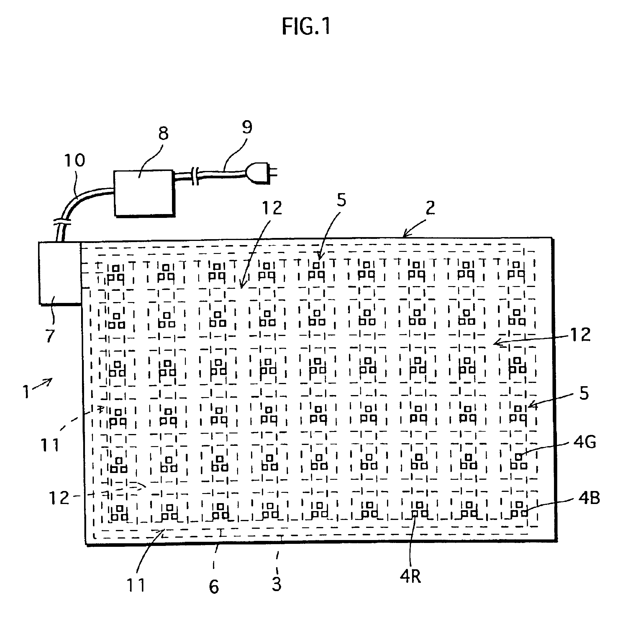
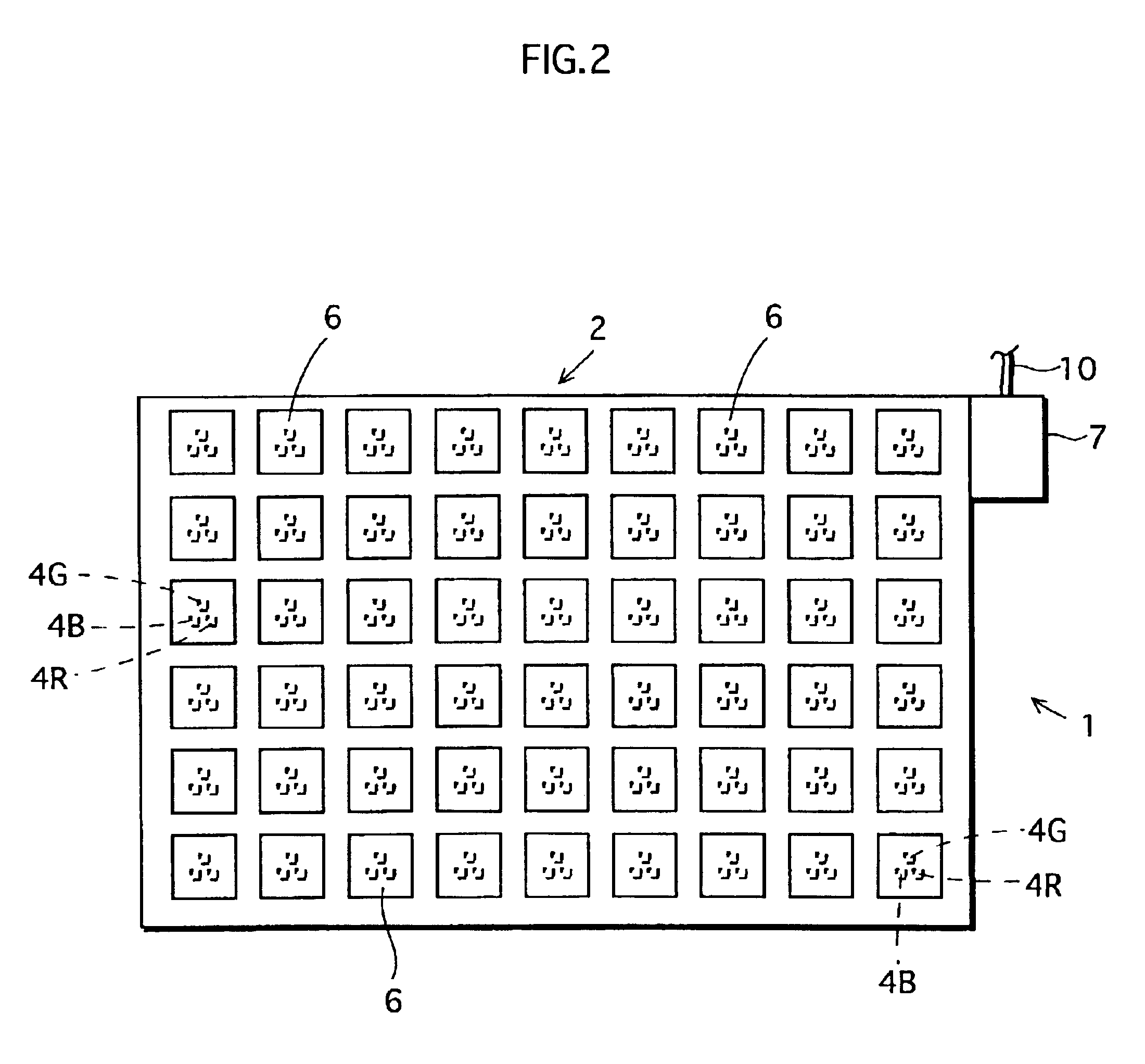
FIG. 1 is a plan view of the whole substrate in the lighting apparatus of the present invention. FIG. 2 is a plan view from the bottom surface of the substrate in the lighting apparatus. As shown in FIG. 1 and FIG. 2, the lighting apparatus 1 comprises a substrate 2 that is flexible, wiring patterns 3 formed on the top surface of the substrate 2, a plurality of LED groups 5 mounted on the wiring patterns 3 on the substrate 2, each of the LED groups 5 being made up of three LEDs 4R, 4G or 4B, a plurality of heat dissipation boards 6 (see FIG. 2) attached on the bottom surface of the substrate 2 at the areas corresponding to the positioning areas of the LED groups 5 on the top surface, a power supply terminal 7 connected to the wiring patterns 3, a controller 8 that is connected with the power supply terminal 7 and that controls the power supplied to the LEDs 4R, 4G, and 4B, and a power cable 9 that is connected to a power supply which is not show...

second embodiment

FIG. 7 is a plan view of an example of the lighting apparatus in the second embodiment of the present invention. FIG. 8 is a plan view from the bottom surface of the substrate in the second embodiment.

In the first embodiment, the heat dissipation boards 6 are attached to the bottom surface of the substrate 2 at the areas corresponding to the positioning areas of each of the LED groups 5. In other words, the positioning area of one LED group 5 is reinforced by one heat dissipation board 6.

On the other hand, in the second embodiment as shown in FIGS. 7 and 8, only one heat dissipation board 30 is attached on the bottom surface of the substrate 2 for a plurality of LED groups 5 together or, for example, for all of the LED groups 5. And then, the heat dissipation board 30 has a plurality of openings 31 at the areas that correspond to the non-positioning areas 12, so that the substrate 2 bends at the areas between LED groups 5. Since some of the components mentioned in the second embodim...


PUM


Abstract

A plurality of groups of Light Emitting Diodes (LEDs), each group being made up of three LEDs with red, green, and blue luminous colors respectively, are mounted at positioning areas of a flexible substrate, on the wiring patterns formed on the top surface of the substrate. A plurality of heat dissipation boards are adhered to the bottom surface of the substrate using an adhesive so as to cover the areas corresponding to the positioning areas of the groups of LEDs.

Description

This application is based on an application No. 2001-284108 filed in Japan, the content of which is hereby incorporated by reference.BACKGROUND OF THE INVENTION(1) Field of the InventionThe present invention relates to lighting apparatuses with light emitting elements mounted thereon, particularly lighting apparatuses that are free to bend.(2) Description of the Related ArtLight Emitting Diodes (hereafter referred to as LEDs) have been attracting attention as a next-generation light source for their long life spans and future possibilities of having high luminous efficacy. Also, there are ideas to use LEDs in thin-type lighting apparatuses since LEDs are more compact than light sources of the prior art. For example, there is an idea of making a columnar pillar into a lighting fixture by adhering a lighting apparatus with LEDs to the surface of the pillar, in which case, the lighting apparatus needs to bend along the surface of the pillar.One of the problems is that when a flexible s...

Claims


Application Information

Patent Timeline
IPC IPC(8): F21V29/00H01L25/075H01L33/00F21S8/04F21V5/04F21Y101/02H01L33/58H01L33/60H01L33/62H01L33/64
CPCF21V29/004F21V29/89H05K1/0281F21V29/2212F21Y2101/02F21Y2105/001H01L25/0753H01L33/64H05K1/0203H05K1/189H05K3/0061H05K2201/10106H05K2201/2009Y10S362/80H01L2224/48091H01L2224/73265H01L2224/45144H01L2924/00H01L2924/3511F21Y2105/10F21Y2115/10H01L2924/00014
Inventor MATSUI, NOBUYUKINAGAI, HIDEOTAMURA, TETSUSHI
Owner PANASONIC CORP
Why Eureka
Try Eureka