Connector with movable contact elements

a technology of contact elements and contact elements, which is applied in the direction of electrically conductive connections, coupling device connections, rotary current collectors, etc., can solve the problem that the spring itself is hardly suited for bonding, and achieve good radiofrequency properties

Inactive Publication Date: 2005-02-22
HARTING ELEKTRO OPTISCHE BAUTEILE
View PDF15 Cites 19 Cited by
  • Summary
  • Abstract
  • Description
  • Claims
  • Application Information

AI Technical Summary

Benefits of technology

In accordance with a first embodiment of the invention, the contact elements are contact balls which are movably arranged in the guide hole. Contact balls are easy to produce. In addition, during insertion of the plug-in card the contact balls partly roll on the surface thereof, whereby a very good self-cleaning is obtained, not only between the plug-in card and the contact ball, but also between the contact ball and the conductor path of the connector.
In the case of the shielded conductor foil it is preferably provided that two conductor paths each are designed as symmetrical conductor pairs, in order to achieve a high signal transmission quality.

Problems solved by technology

The spring itself, however, is hardly suited for bonding when RF signals are to be transmitted; with regard to the required spring characteristics, the spring must be very much larger than is expedient for the transmission of RF signals.

Method used


Image

  • Connector with movable contact elements
  • Connector with movable contact elements
  • Connector with movable contact elements

Examples


first embodiment

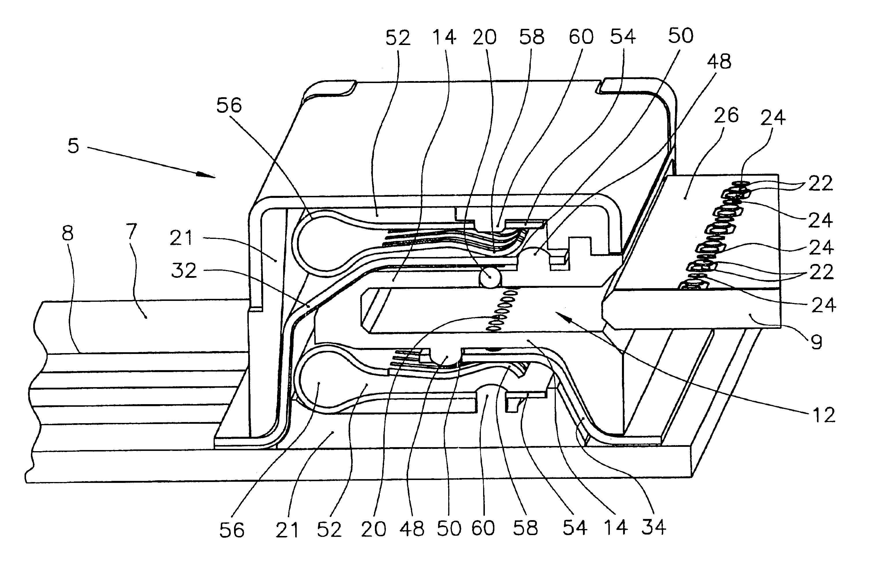
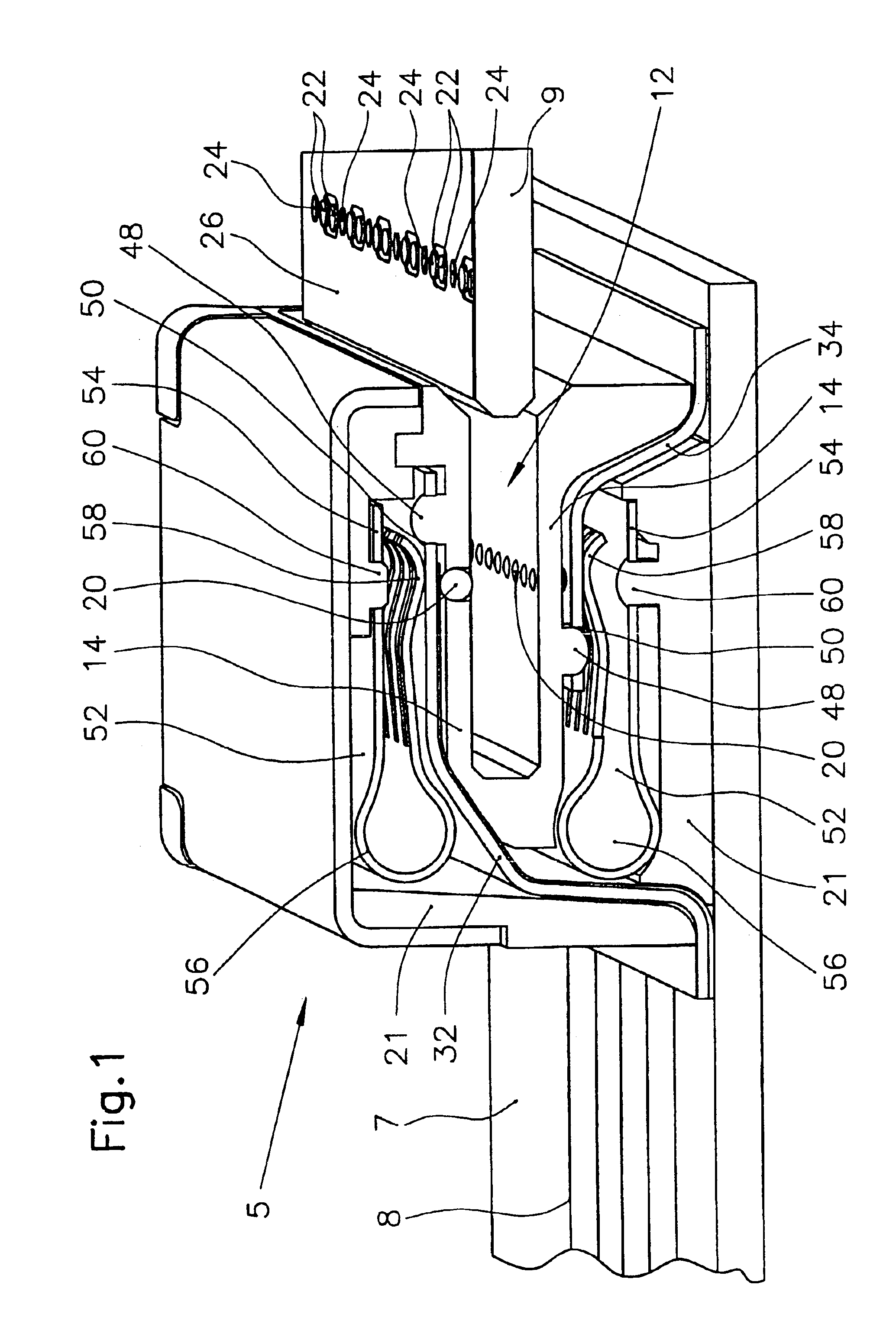
FIG. 1 shows a connector 5 in accordance with a This connector is arranged on a printed circuit board 7, which is provided with schematically indicated conductor paths 8. Into the connector 5, a plug-in card 9 can be inserted such that conductor paths of the plug-in card 9 are bonded electrically.

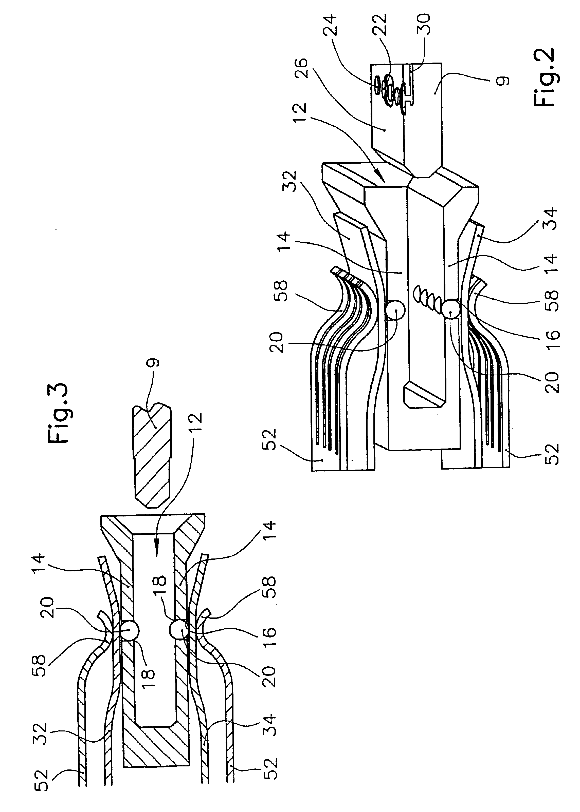
As central component, the connector 5 has a carrier 10 in which a receiving space 12 of rectangular cross-section is formed for the plug-in card 9. The carrier 10 is made of an electrically insulating material, in particular plastics. In the two larger side walls 14 of the carrier 10, there is formed a plurality of guide holes 16 disposed one beside the other in a row, which extend as through hole from the receiving space 12 through the side wall 14 towards the outside. Each guide hole 16 constitutes a bore of circular cross-section, and on its side facing the receiving space 12 a collar 18 is provided, whose inside diameter is smaller than the diameter of the remaining portion of the guid...

second embodiment

The advantage of the second embodiment consists in that the guide holes can be designed to continuously have the same diameter; there is not required a constriction of the guide hole 16, in order to form a stop for the contact element. Another advantage should consist in that contact pins are basically better suited for the transmission of RF signals than contact balls.


PUM


Abstract

A connector for receiving a plug-in card comprises a carrier which defines a receiving space for the plug-in card, at least one guide hole which is formed in the carrier and which opens in the receiving space, a contact element which is movably arranged in the guide hole, a spring which urges the contact element towards the receiving space, and a conductor path which is electrically connected with the contact element.

Description

This invention relates to a connector for receiving a plug-in card. The invention in particular relates to a connector for bonding an electrooptical transceiver, wherein signal transmission rates of about 10 Gbit per second are possible.BACKGROUND OF THE INVENTIONVarious connectors are known, which are used for signal transmission at high signal transmission rates, and which should ensure a particularly high signal transmission quality. Usually, first and second connector parts are used, one of which is mounted for instance on a carrier card and the other one is mounted on the component to be connected, for instance on the electrooptical transceiver. When inserting the plug-in card into its mount, the two connector parts are also inserted in each other.The object of the invention consists in creating a connector which provides for a high signal transmission quality with a high signal transmission rate and little effort. The object of the invention in particular consists in creating ...

Claims


Application Information

Patent Timeline
Patent Type & Authority Patents(United States)
IPC IPC(8): H01R4/52H01R4/50H01R12/50H01R12/61H01R12/71H01R12/79H05K1/11
CPCH01R12/79H01R4/5058H01R4/52H01R12/714H01R23/6873H01R12/613H01R13/658
Inventor BURMEISTER, MICHAEL
Owner HARTING ELEKTRO OPTISCHE BAUTEILE
Why Eureka
Try Eureka