Ankle brace with cuff and strap

a technology of ankle braces and cuffs, applied in the field of ankle braces, can solve the problems of sacrificing some structural support, irritation and pain, and less support for the person's ankle, and achieve the effects of improving flexibility, improving stability, and improving stability

Inactive Publication Date: 2005-02-22
ULTRA ATHLETE
View PDF34 Cites 39 Cited by
  • Summary
  • Abstract
  • Description
  • Claims
  • Application Information

AI Technical Summary

Benefits of technology

The present invention provides the desired front-to-back flexibility of the prior art braces, and, in addition, provides improved structure so that there is additional structural support preventing side-to-side movement of the ankle.
In particular, most of the preferred embodiments of the present invention provide arms, extending from the left and right pivot legs, which are joined together to form a flexible rear cuff. The phrase “flexible rear cuff” means a rear cuff that provides greater flexibility than would be provided by joining the arms together to form the cuff as a unitary piece having substantially the same thickness, continuity, and height as the arms themselves The flexibility may be achieved by cutting out portions of the unitary rear cuff to make it substantially more flexible, or by changing the dimensions of a portion of the unitary rear cuff so that it is substantially thinner or shorter than the arms, or both, thereby creating a substantially more flexible section. Also, if the arms are not formed as a unitary piece, the mechanical arrangement by which the arms are joined together to form the cuff may provide the flexibility. For example, in one preferred embodiment, the arms are connected together by a rivet which permits them to pivot relative to each other. This pivot connection allows the brace to be adjusted in order to fit a wide variety of people's foot and leg shapes, resulting in a comfortable brace, while providing more support than prior art designs. The arms, pivoted together, limit the range of motion between the pivot legs while providing the desired flexibility so that the wearer can continue to flex and exercise the ankle while the ankle is protected and supported by the brace. Most of the other embodiments use other mechanisms for providing a controlled, flexible connection between the arms.
The preferred embodiments of the present invention also provide a heel stirrup and a tongue, extending forward of the heel stirrup. The heel stirrup surrounds the heel to provide the greatest possible stability while leaving the bottom of the foot, including the arch, free to spread out, so that the stirrup does not impinge on the wearer's foot.
The preferred embodiments of the present invention also provide an ankle brace with a single strap closure mechanism that provides the wearer easy enhanced structural support, adjustability for ankle size, and ease of use.

Problems solved by technology

While the straps provide flexibility of movement, they also stretch and shift, thereby sacrificing some structural support.
Also, in prior art designs, the semi-rigid stirrup encircled the bottom of the foot, interfering with a person's foot spreading out as he put his weight on the foot, thereby causing irritation and pain.
If the stirrup were made wide enough to avoid that problem, it would provide less support to the person's ankle and might be too wide to fit into the person's shoe.

Method used


Image

  • Ankle brace with cuff and strap
  • Ankle brace with cuff and strap
  • Ankle brace with cuff and strap

Examples


Embodiment Construction

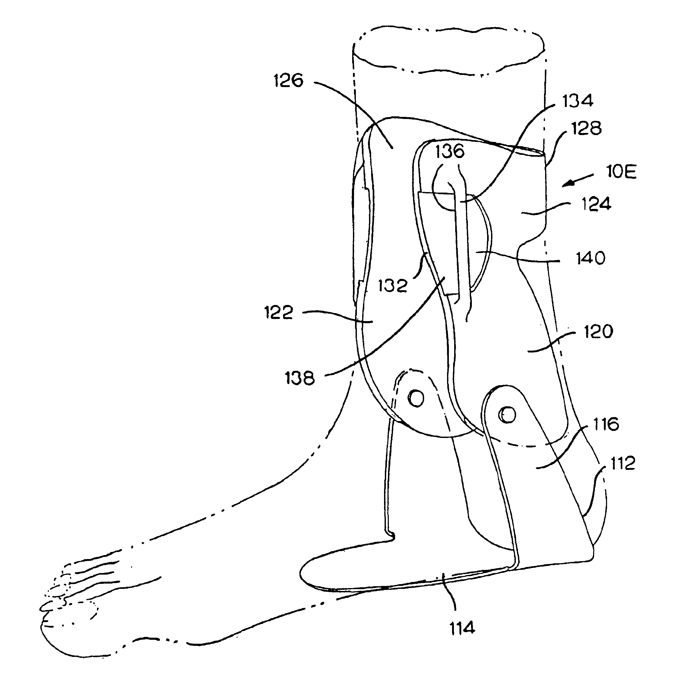
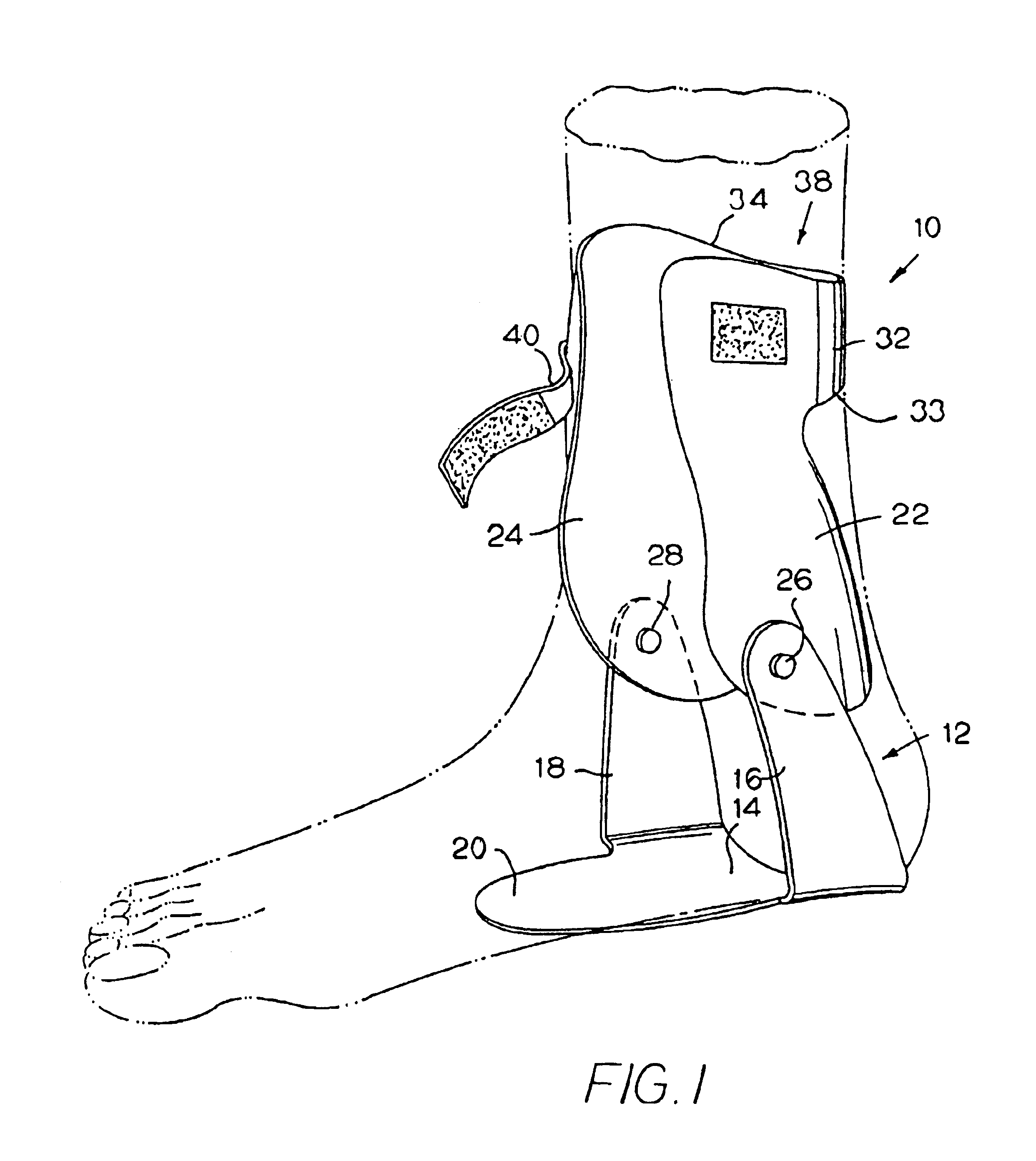
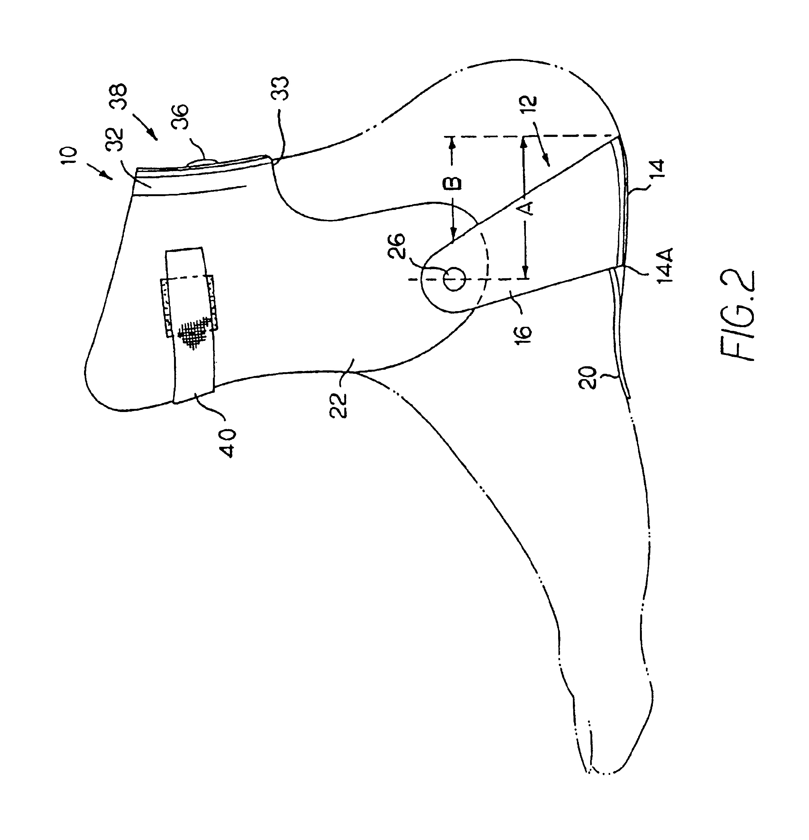
FIGS. 1-5 show an ankle brace 10, which is made up of three main pieces. The first piece is the heel stirrup 12, which is substantially U-shaped, and includes a base or bottom portion 14 and left and right upright portions 16, 18. The upright portions 16, 18 project upwardly and forwardly from the rear of the base portion 14, which permits them to wrap around the heel, which provides for the greatest support, while still locating the pivots 26, 28 adjacent to the ankle, to provide the greatest comfort and flexibility. The horizontal distance “A” from the axis of the pivots 26, 28 to the rear of the stirrup 12 preferably is at least one inch. The horizontal distance “B” from the rear edge of the upright portion 16 at the height of the pivot 26 to the rear edge of the base 14 preferably is at least 0.75 inches. This location of the upright portions 16, 18 also prevents the stirrup 12 from interfering with the spreading of the foot. A tongue 20 extends forward from the forward edge 14A...


PUM


Abstract

An ankle brace includes a heel stirrup including a base and left and right upright portions. Left and right pivot legs are pivotably connected to the left and right uprights, respectively. A cuff joins the left and right pivot legs. In most preferred embodiments, the rear cuff is flexible.

Description

BACKGROUND OF THE INVENTIONThe present invention relates to ankle braces, and, in particular, to an ankle brace that provides greater comfort and support than braces of the prior art.Many types of ankle braces are known, including my earlier design, described in U.S. Pat. No. Re. 33,395. That brace provided greater flexibility and comfort than other braces, because it provided pivots on both sides of the brace, which enabled the foot to flex forward and backward while limiting side-to-side motion of the foot relative to the leg in order to protect the injured ankle. That brace had left and right pivot legs, which were intended to lie along the left and right sides of the wearer's leg, and there were straps which wrapped around the leg to hold the pivot legs together. While the straps provide flexibility of movement, they also stretch and shift, thereby sacrificing some structural support.Also, in prior art designs, the semi-rigid stirrup encircled the bottom of the foot, interfering...

Claims


Application Information

Patent Timeline
Patent Type & Authority Patents(United States)
IPC IPC(8): A61F5/01
CPCA61F5/0127
Inventor PETERS, RICK E.
Owner ULTRA ATHLETE
Why Eureka
Try Eureka