Multi-axial bone anchor system

a multi-axial, bone anchoring technology, applied in the field of orthopedic implants, can solve the problem that the apparatus does not provide the preferred multi-axial capability, and achieve the effect of improving multi-axial capability, superior strength and ease of us

Inactive Publication Date: 2005-02-22
SDGI HLDG
View PDF29 Cites 251 Cited by
  • Summary
  • Abstract
  • Description
  • Claims
  • Application Information

AI Technical Summary

Benefits of technology

It is therefore an object of this invention to provide a spinal implant system having improved mu...

Problems solved by technology

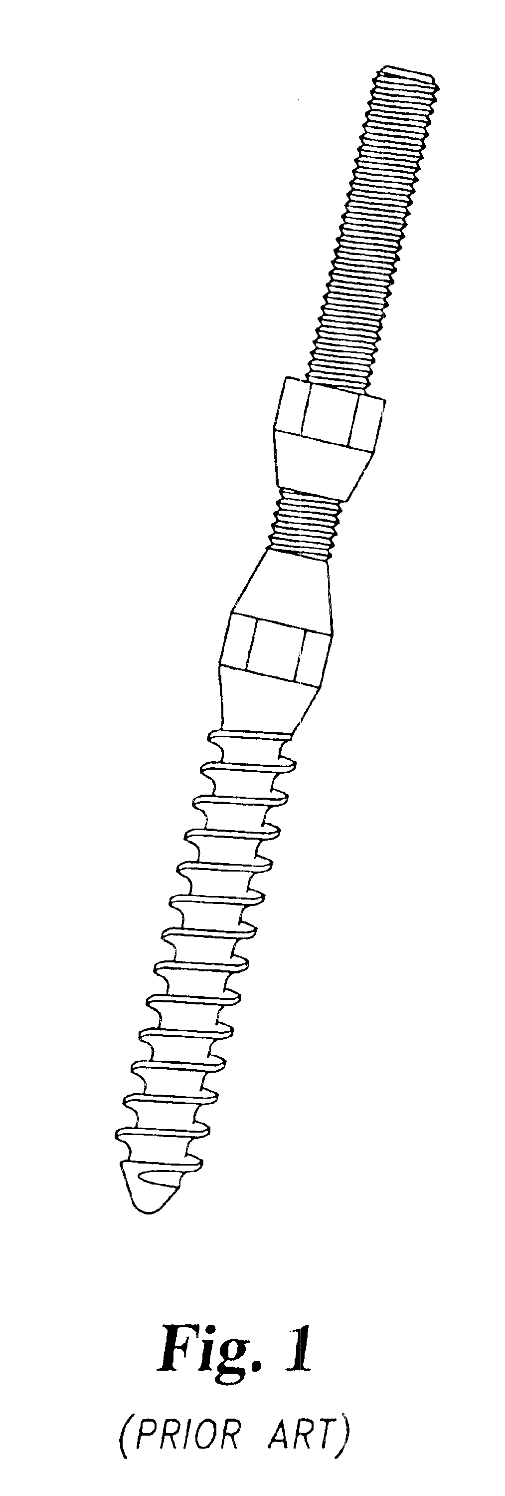
This apparatus does not provide the prefe...

Method used


Image

  • Multi-axial bone anchor system
  • Multi-axial bone anchor system
  • Multi-axial bone anchor system

Examples


second embodiment

stabilizer 26′ is illustrated in FIGS. 16a-16c. Stabilizer 26′ is like stabilizer 26 in most respects. However, stabilizer 26′ has a body 90′ approximately in the shape of a parallelogram. Finger portions 92′, bore 94′ and tapered wall 96′ are substantially similar to finger portions 92, bore 94, and tapered wall 96 of stabilizer 26, described and illustrated above. As noted above, alternative configurations of the walls of bore 94′ are contemplated as being within the scope of the present invention. For example, tapered wall 96′ could be contiguous with or separate from a cylindrical wall which also bounds bore 94′. Fingers 92′ are shaped in dimension to fit within slot 39 of elongated member 22 such that FIG. 92′ abut ledges 36 and under surface 37 of elongated member 22. One or more stabilizers 26′ may be inserted into slot 39 via an open end of elongated member 22, and until implant system 20 is finally tightened or locked as described below, are slideable along ledges 36 of elo...

embodiment 99

An alternative embodiment 99 of the present invention is illustrated in FIGS. 8-13. Referring generally to FIG. 8, there is shown an elongated member 100 according to that alternative embodiment. Elongated member 100 includes a superior end 102, an inferior or caudal end 104, and a longitudinal axis 106 generally extending there between. Typically, when implanted superior end 102 and inferior end 104 will be oriented as cephalad and caudal ends, respectively.

Superior end 102 includes a pair of longitudinal slots 108 and 110, which are placed transversely of each other. Slot 108 has a configuration very similar to the arrangement of slot 30 in elongated member 22. Slot 108 includes a ledge 112 near the upper part of elongated 100, which substantially encircles slot 108 in one specific embodiment. It is contemplated that in another embodiment, slot 108 may include two ledges 112, each running along substantially the entire length of a longitudinal side of slot 108. Preferably, side wa...


PUM


Abstract

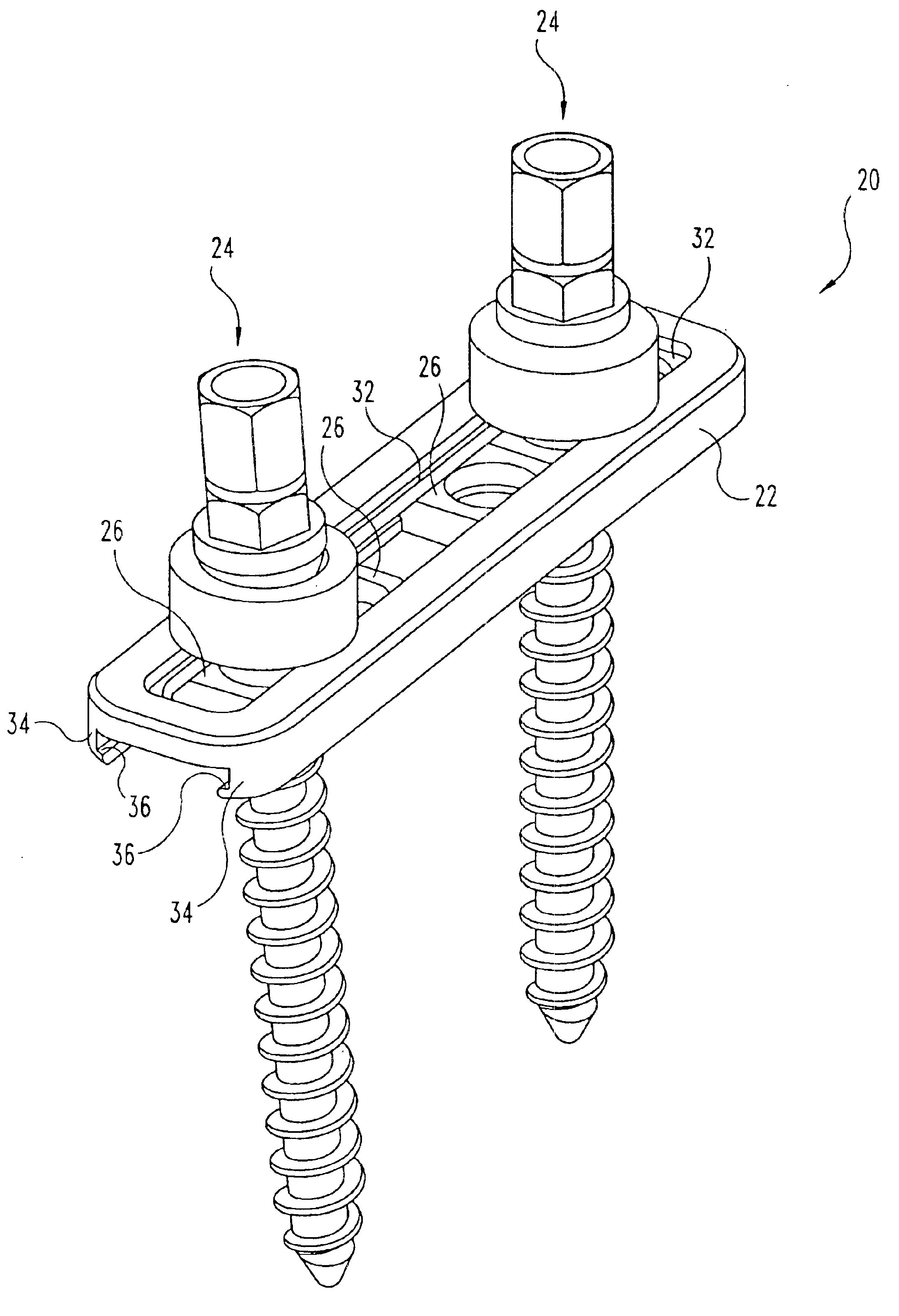
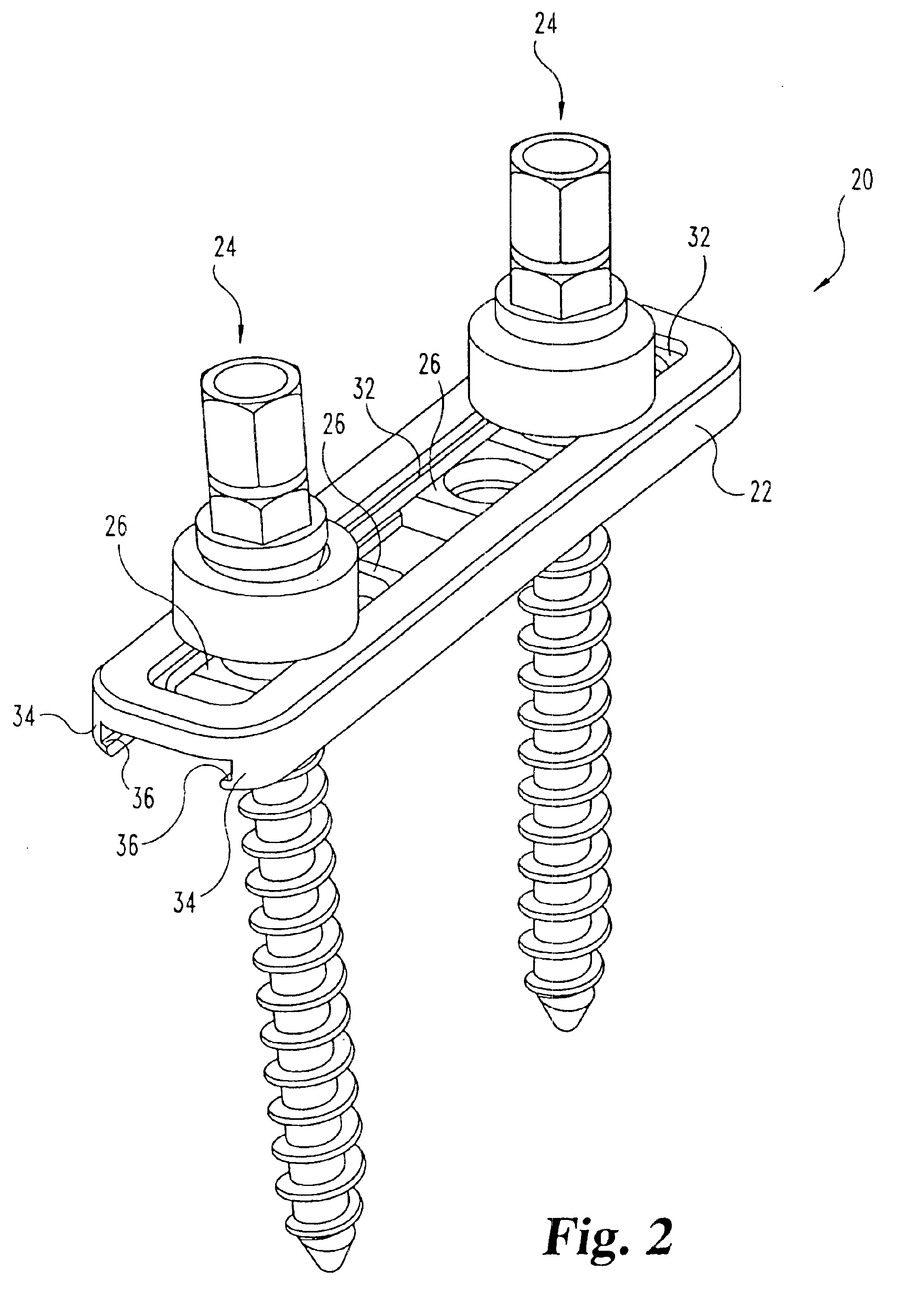
A spinal implant system is disclosed for the fixation of bone segments in the spine. The system includes an elongated member, one or more bone anchor assemblies, and stabilizer members which are fitted within the elongated member. A bone anchor is attached to a bone, and the elongated member and stabilizer are fitted over the bone anchor. A rounded washer and nut having a corresponding rounded underside surface are fitted on to the bone anchor over the elongated member, and tightened. The configuration of the bone anchor assembly, including an intermediate portion of the bone anchor, the arcuate washer, and the nut, along with the configuration of the sliding support, allows multi-axial positioning of the bone anchor with respect to the elongated member at a plurality of locations along a slotted member.

Description

FIELD OF THE INVENTIONThe present invention concerns orthopedic implants, particularly for the spine or long bones. Specifically, the present invention includes a bone anchor system having multi-axial capabilities, which may be used in conjunction with an orthopedic implant device such as a spinal plate or rod system.BACKGROUND OF THE INVENTIONIn the art of orthopedic surgery, and particularly in spinal surgery, it has long been known to affix an elongated member, such as a plate or rod, to bones in order to hold them and support them in a given position. For example, in a procedure to fuse damaged vertebrae, the vertebrae are positioned in a corrected position as required by the surgeon. A plate is placed adjacent to the bone, and bone anchors are employed to secure the plate to the bones. Bone screws or bolts are commonly utilized as the bone anchors, and with such anchors placement is accomplished by drilling one or more holes in the bone(s), and threading the anchors into the ho...

Claims


Application Information

Patent Timeline
IPC IPC(8): A61B17/70A61B19/00A61B17/58
CPCA61B17/7007A61B17/701A61B17/7011A61B17/7035A61B17/7058A61B17/8033A61B17/8047A61B17/7041A61B17/7037A61B2019/307A61B17/8695A61B2090/037
Inventor MORRISON, MATTHEW M.BARKER, B. THOMASYOUNG, JOHN STEWARTBEALE, JEFFREY W.JOHNSON, CHRIS E.
Owner SDGI HLDG
Why Eureka
Try Eureka