Self-aligning driveshaft coupler

a drive shaft and self-aligning technology, which is applied in the direction of couplings, agricultural machines, transportation and packaging, etc., can solve the problems of difficult and dirty coupling of tractor pto to the driveline of the implement, time-consuming and manual coupling of the power take off to the implement, and difficult to find the correct alignment of the female spline of the drive line, so as to improve the safety of the operator and facilitate us

Active Publication Date: 2016-08-18
DEERE & CO
View PDF14 Cites 8 Cited by
  • Summary
  • Abstract
  • Description
  • Claims
  • Application Information

AI Technical Summary

Benefits of technology

[0008]The self-aligning driveshaft coupler provides greater operator safety and ease of use when hooking up a tractor PTO to the shaft of an implement. It may be used with standard PTO driveshafts on tractors, and with standard shafts or drivelines on a variety of different implements. The self-aligning driveshaft coupler also does not require any external energy source such as electricity, hydraulics or pneumatics

Problems solved by technology

This requires getting down off the seat or operator station of the tractor, and it can be quite time consuming to couple the power take off to the implement manually.
Coupling a tractor PTO to the driveline of an implement also can be difficult and dirty.
Often it is difficult to find the correct alignment for the female spline of the drive line and the male spline of the tractor PTO.
It may be difficult to manipulate the lock back feature or turn the implement driveline to obtain correct alignment between the PTO and the implement shaft.

Method used


Image

  • Self-aligning driveshaft coupler
  • Self-aligning driveshaft coupler
  • Self-aligning driveshaft coupler

Examples


Embodiment Construction

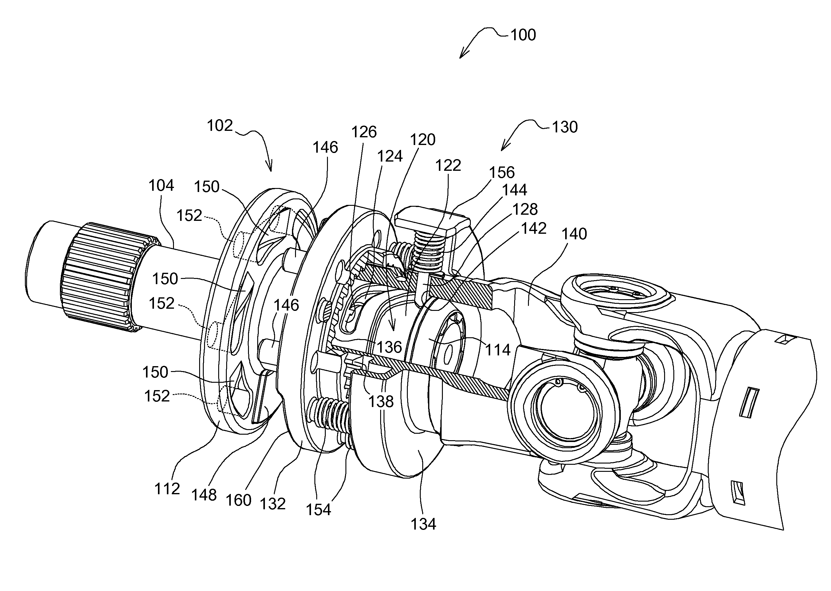
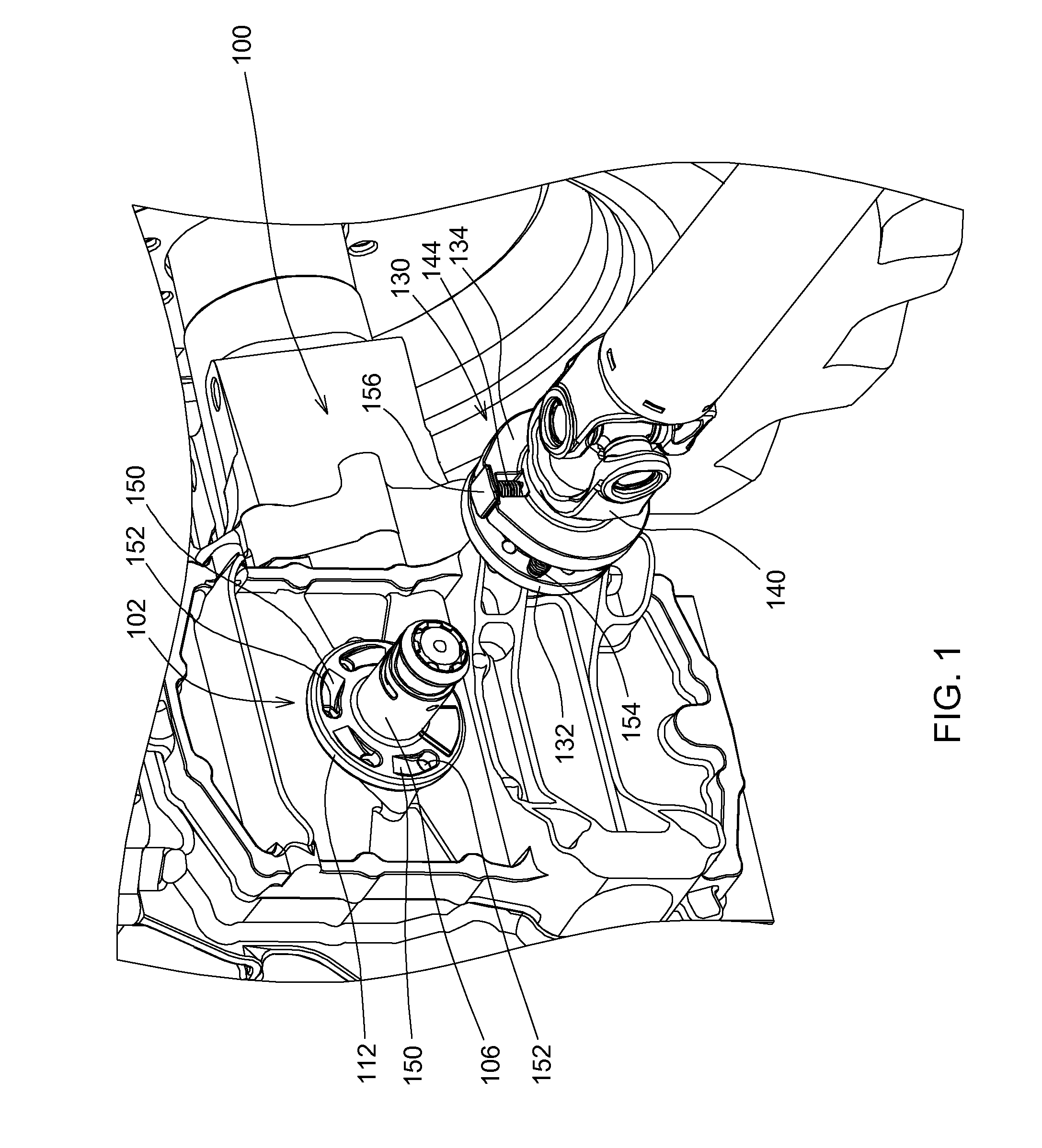
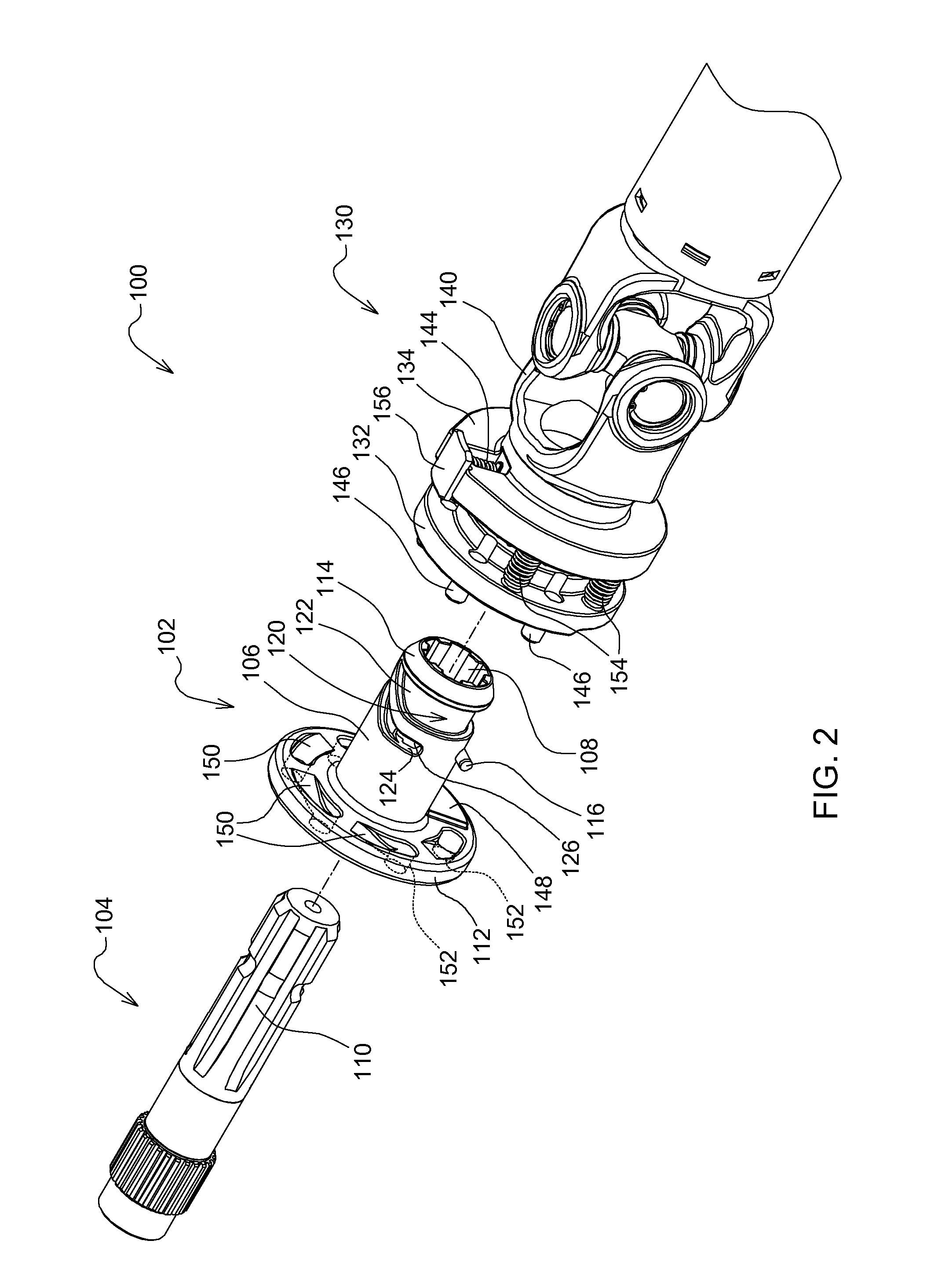
[0014]As shown in FIGS. 1-5, self-aligning driveshaft coupler 100 may be used to connect a tractor PTO to a driveline or shaft of a rear mounted implement. The self-aligning driveshaft coupler may include receiving clutch 102 installed and mounted to tractor PTO output shaft 104. The receiving clutch may include neck 106 with internal splines 108 that fit around and engage the external splines 110 on a standard tractor PTO output shaft. The neck may be integral with base or flange 112. The outer end 114 of the neck may have a sloped lip that does not extend beyond the end of the tractor PTO output shaft. The receiving clutch may be secured to the tractor PTO output shaft using pin 116 inserted through radial hole 118 in the neck and a corresponding hole in the tractor PTO output shaft. Other similar devices may be used to secure the receiving clutch axially to the tractor PTO output shaft.

[0015]In one embodiment, the self-aligning driveshaft coupler may include a spiral channel 120 ...


PUM


Abstract

A self-aligning driveshaft coupler includes a receiving clutch having a spiral channel around its neck, and a locking clutch assembly with a first ring shaped member and a second ring shaped member that rotate together. A locking pin extends radially from the second ring shaped member and into the spiral channel and pulls the locking clutch assembly toward the receiving clutch as the receiving clutch rotates. A plurality of drive pins extend axially from the first ring shaped member and engage the receiving clutch when the locking pin is at the end of the spiral channel.

Description

FIELD OF THE INVENTION[0001]This invention relates generally to coupler devices between tractor power take offs and agricultural implements, and specifically to quick connect couplers for coupling power take offs to driveshafts of rear mounted implements.BACKGROUND OF THE INVENTION[0002]Tractors may be equipped with a power take off (PTO) that transmits rotary power from an engine to an implement. The most common location for the PTO shaft is at the rear of the tractor, but some tractors have auxiliary PTO shafts at other locations. The direction of rotation, rotational speed, approximate location and exact dimensions of the PTO shaft are standardized to provide ability to interchange between power shafts on various implements made by different manufacturers. PTO shafts typically rotate at 540 rpm, 1000 rpm, 2100 rpm, or more than one speed.[0003]To engage the PTO to the shaft or drive line of a rear mounted implement, the PTO may have the ability to telescope. After the tractor is ...

Claims


Application Information

Patent Timeline
Patent Type & Authority Applications(United States)
IPC IPC(8): F16D1/108F16D3/16
CPCA01B71/06B60K17/28F16D3/16F16D1/108B60Y2200/221F16D47/02Y10S464/901Y10S464/905F16D3/387F16D2001/103
Inventor KNUTH, THOMAS M.
Owner DEERE & CO
Why Eureka
Try Eureka