Procedure for shutting down a fuel cell system using air purge

a fuel cell and air purge technology, applied in the direction of fuel cells, solid electrolyte fuel cells, fuel cells, etc., can solve the problems of affecting the performance the large number of start/stop cycles, and the rapid performance decay of the cell stack assembly, so as to reduce the period of time, reduce the amount of fuel cell catalyst and catalyst support corrosion, and reduce the effect of cathode potential

Inactive Publication Date: 2005-02-22
AUDI AG
View PDF11 Cites 66 Cited by
  • Summary
  • Abstract
  • Description
  • Claims
  • Application Information

AI Technical Summary

Benefits of technology

One object of the present invention is to minimize any fuel cell catalyst and catalyst support corrosion occurring during shut-down of the fuel cell, and to do it without purging air from the cells with inert gas upon shut-down.
In accordance with one embodiment of the present invention, a shut-down procedure includes the steps of disconnecting the primary load from the cell; halting the flow of fuel to the anode and the flow of air to the cathode; and then blowing air under pressure into and through the anode flow field to rapidly displace all the hydrogen remaining in the anode flow field. Displacing the hydrogen quickly reduces the period of time that platinum and carbon corrosion occurs, as compared with simply allowing the air to be drawn slowly into the cell as a result of falling hydrogen pressure over an extended period of time, which may be as long as 30 to 60 seconds or more. Although dependent upon the cell materials, desired length of cell life, and the number of shut-downs and start-ups likely to occur during that life, it is believed the hydrogen / air front will need to move through the anode in no more than about 1.0 second to satisfy performance needs over the life of the cell without requiring an inert gas purge. Preferably the purge air flow rate will move the H2 / air front (and thus all the hydrogen) through and out of the anode flow field in less than 0.2 seconds. For long life applications, such as automotive applications, with frequent start-ups and shut-downs, a purge time of 0.05 seconds or less is most preferable.
In a preferred embodiment of the invention, after the primary load is disconnected and the fuel and oxidant flow to the cell is stopped, a small auxiliary resistive load is connected across the cell for a period of time immediately prior to blowing air through the anode flow field. The application of the auxiliary load prior to the purging step consumes hydrogen in the anode flow field through the occurrence of normal electrochemical reactions. Then, when the step of blowing air through the anode flow field commences, the cathode potential will have been significantly lowered, and, consequently, the rate of catalyst and catalyst support corrosion during the air purge will be lower. Note that, in this embodiment, the auxiliary load may be disconnected prior to commencing the air purge, or it may be continued during at least a portion of or throughout the air purge.
In the preceding preferred embodiment the auxiliary load is connected after stopping both the fuel and oxidant flow to the cell. This reduces the cathode potential by consuming all the residual oxygen in the cathode flow field and a significant amount of the residual hydrogen in the anode flow field. Alternatively, the auxiliary load is connected after the oxidant flow has been stopped, but prior to stopping the fuel flow. The fuel flow is stopped at any time prior to commencing the air purge. The auxiliary load remains connected at least until the residual oxygen on the cathode has been consumed. The fuel flow is turned off at any time prior to commencing the air purge. Both the preferred and alternate embodiments reduce the cathode potential prior to the air purge. The preferred embodiment, however, assures the maximum possible reduction.

Problems solved by technology

It was found that a cell stack assembly operated in this manner experienced rapid performance decay which had not previously been observed.
Further, it was discovered that a large number of start / stop cycles were more detrimental to cell performance than were a large number of normal operating hours under load.

Method used


Image

  • Procedure for shutting down a fuel cell system using air purge
  • Procedure for shutting down a fuel cell system using air purge
  • Procedure for shutting down a fuel cell system using air purge

Examples


Embodiment Construction

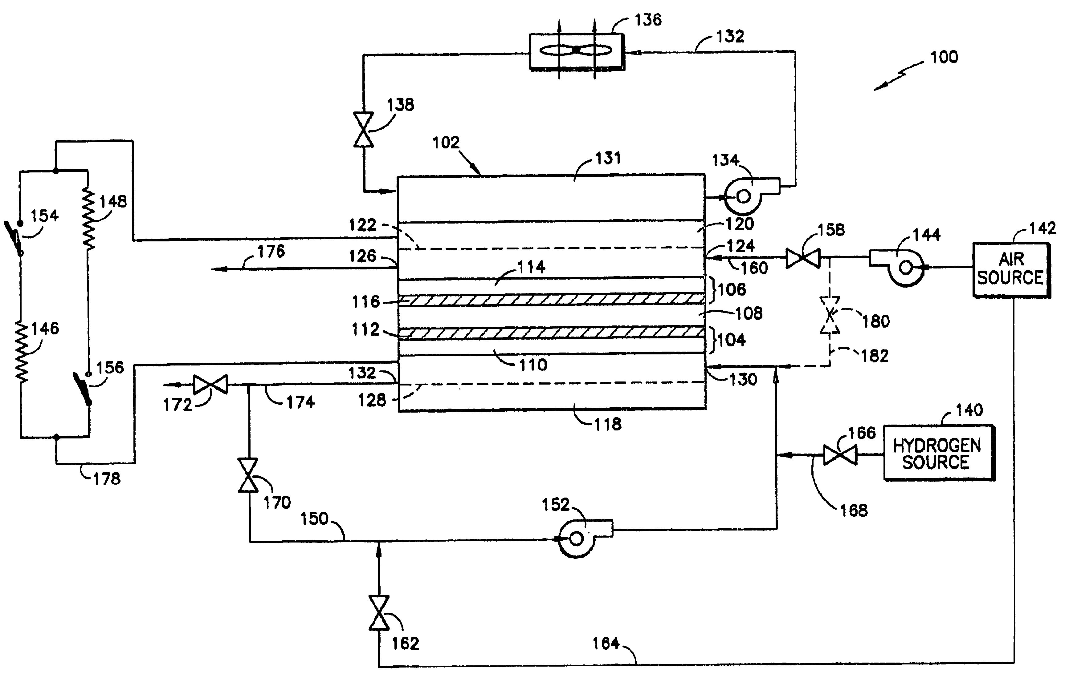
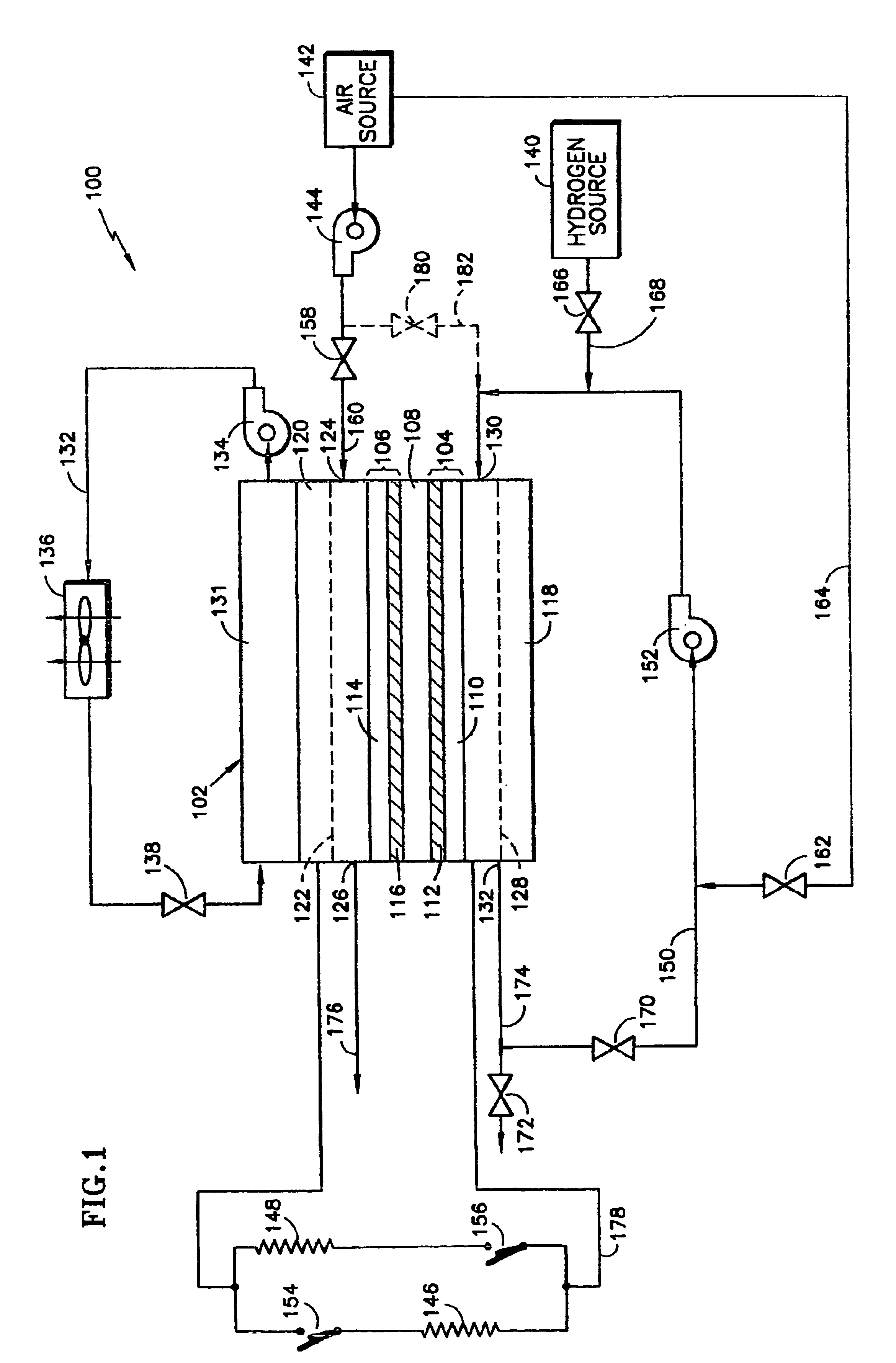
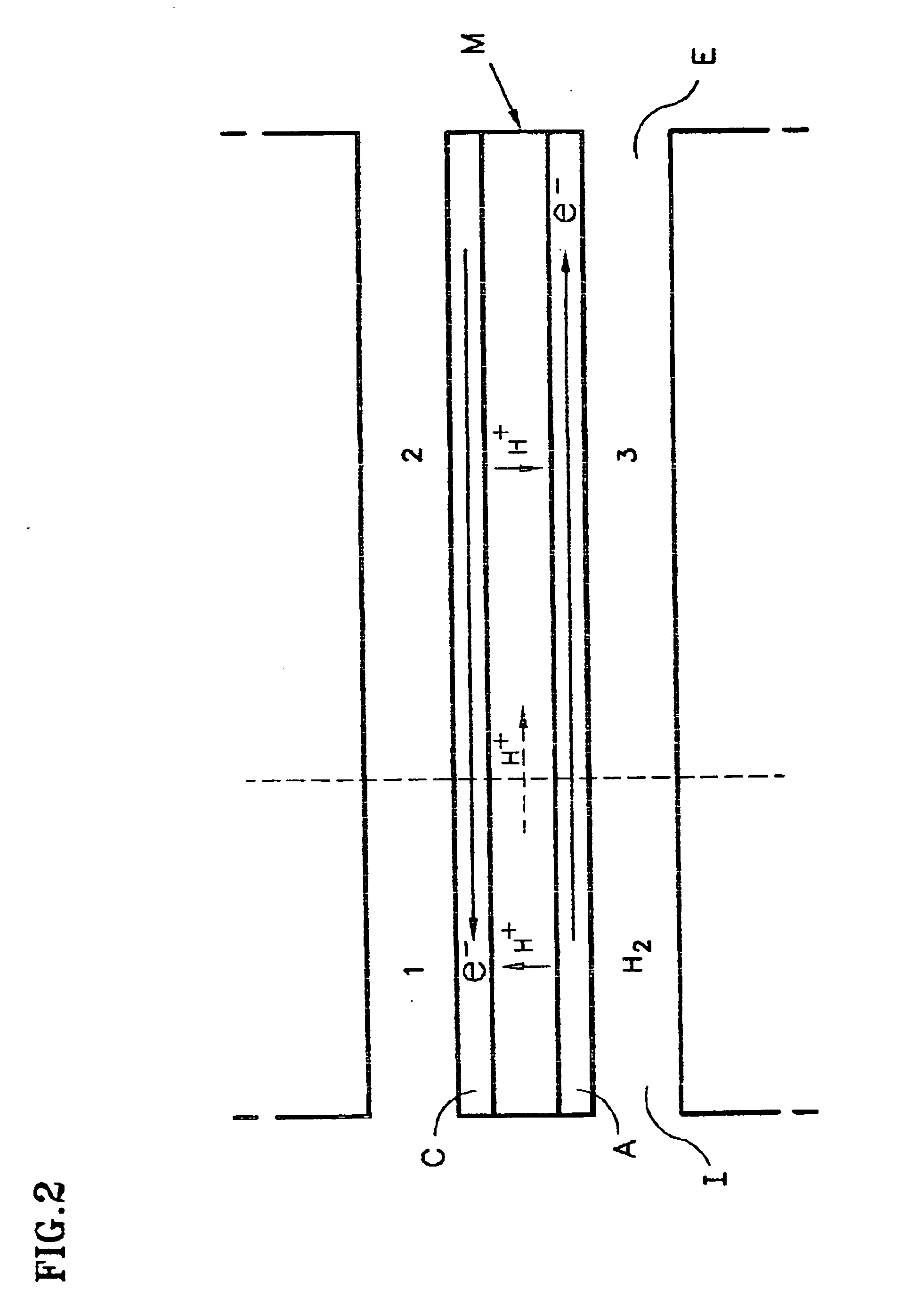
In FIG. 1, a fuel cell system 100 is shown. The system includes a fuel cell 102 comprising an anode 104, a cathode 106, and an electrolyte layer 108 disposed between the anode and cathode. The anode includes an anode substrate 110 having an anode catalyst layer 112 disposed thereon on the side of the substrate facing the electrolyte layer 108. The cathode includes a cathode substrate 114, having a cathode catalyst layer 116 disposed thereon on the side of the substrate facing the electrolyte layer 108. The cell also includes an anode flow field plate 118 adjacent the anode substrate 110, and a cathode flow field plate 120 adjacent the cathode substrate 114.

The cathode flow field plate 120 has a plurality of channels 122 extending thereacross adjacent the cathode substrate forming a cathode flow field for carrying an oxidant, preferably air, across the cathode from an inlet 124 to an outlet 126. The anode flow field plate 118 has a plurality of channels 128 extending thereacross adja...


PUM

PropertyMeasurementUnit
voltageaaaaaaaaaa
voltageaaaaaaaaaa
voltageaaaaaaaaaa

Abstract

A procedure for shutting down an operating fuel cell system includes disconnecting the primary electricity using device and stopping the flow of hydrogen containing fuel to the anode, followed by quickly displacing the residual hydrogen with air by blowing air through the anode fuel flow field. A sufficiently fast purging of the anode flow field with air eliminates the need for purging with an inert gas such as nitrogen.

Description

BACKGROUND OF THE INVENTION1. Technical FieldThis invention relates to fuel cell systems and, more particularly, to procedures for shutting down an operating fuel cell.2. Background InformationIt is well known in the fuel cell art that, when the electrical circuit is opened and there is no longer a load across the cell, such as upon and during shut-down of the cell, the presence of air on the cathode, coupled with hydrogen fuel remaining on the anode, often cause unacceptable anode and cathode potentials, resulting in catalyst and catalyst support oxidation and corrosion and attendant cell performance degradation. It was thought that inert gas needed to be used to purge both the anode flow field and the cathode flow field immediately upon cell shut-down to passivate the anode and cathode so as to minimize or prevent such cell performance degradation. Further, the use of an inert gas purge avoided the possible occurrence of a flammable mixture of hydrogen and air, which is a safety i...

Claims


Application Information

Patent Timeline
Patent Type & Authority Patents(United States)
IPC IPC(8): H01M8/04H01MH01M8/00H01M8/10
CPCH01M8/04223H01M8/04231Y02E60/50H01M8/0258H01M8/0267H01M8/241H01M8/04225H01M8/04228H01M8/04302H01M8/04303H01M8/2457H01M8/04
Inventor REISER, CARL A.YANG, DELIANGSAWYER, RICHARD D.
Owner AUDI AG
Why Eureka
Try Eureka