Electric field proximity detector for floating and grounded targets

a technology of proximity detector and floating ground, applied in the direction of mechanical vibration actuation of burglar alarms, instruments, pulse techniques, etc., can solve the problems of inability of these devices to reliably sense objects with intermediate degrees of ground impedance, and add to the complexity of detector circuitry

Inactive Publication Date: 2005-02-22
APPLE INC
View PDF13 Cites 86 Cited by
  • Summary
  • Abstract
  • Description
  • Claims
  • Application Information

AI Technical Summary

Benefits of technology

It is an object of the present invention to provide a transmit-receive type electric field proximity d

Problems solved by technology

The first drawback is the added complexity in detector circuitry that is required to detect both floating and grounded objects.
This requirement may add to the complexity of detector circuitry, especially if the device is intended to be capable of distinguishing between floating versus grounded objects.
The second and more serious drawback of the two operating modes of known detectors is the resulting inability of these devices to reliably sense objects with intermediate degrees of ground impedance.
Objects having such a degree of ground impedance m

Method used


Image

  • Electric field proximity detector for floating and grounded targets
  • Electric field proximity detector for floating and grounded targets
  • Electric field proximity detector for floating and grounded targets

Examples


Embodiment Construction

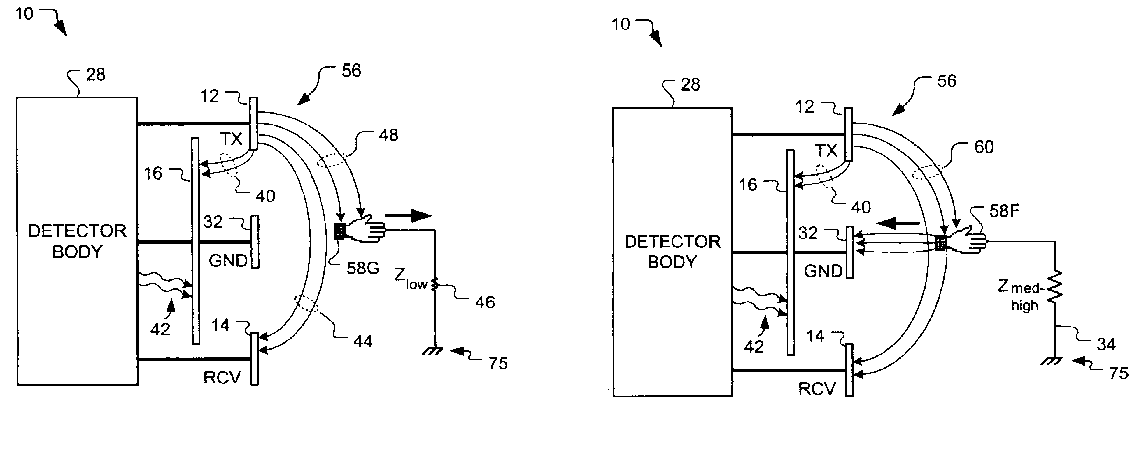
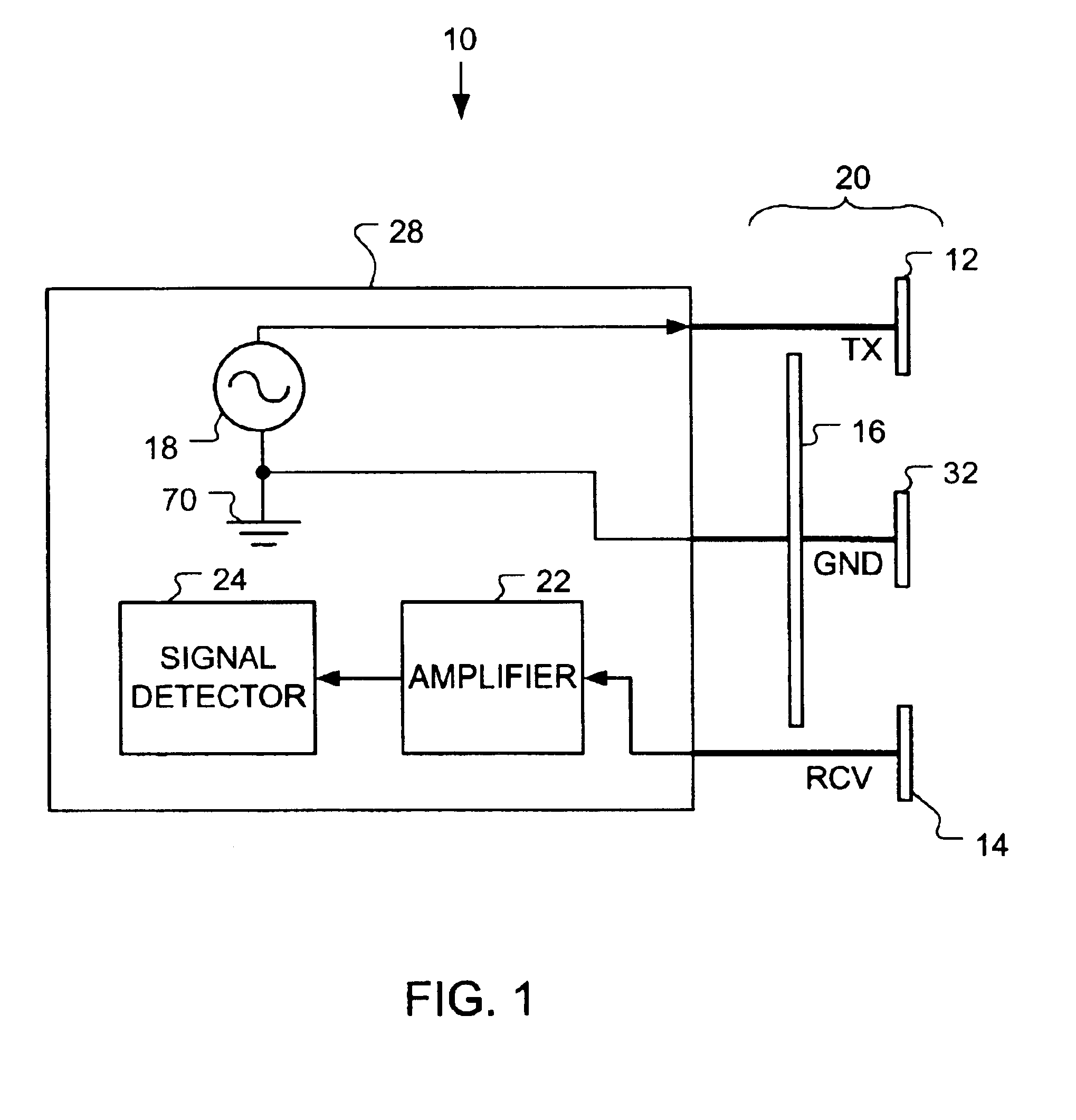
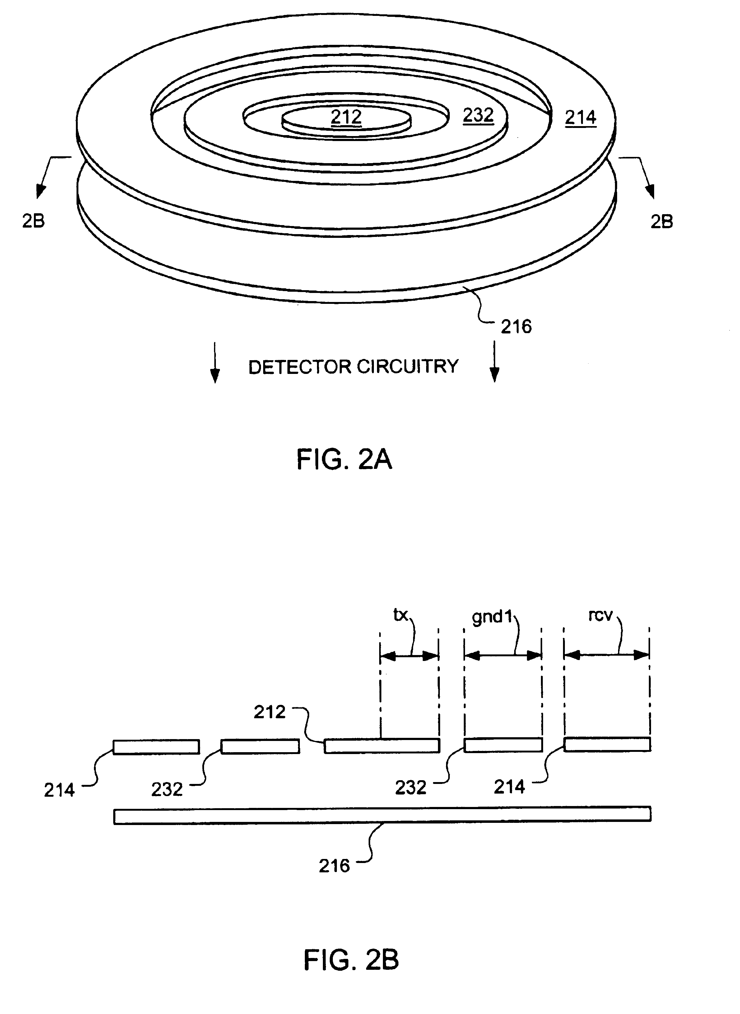
With reference to the schematic diagram of FIG. 1, a proximity detector 10 has a sensor 20 coupled to a detector body 28. The sensor 20 comprises a transmitting electrode 12, a receiving electrode 14, a first ground electrode 32 and a second ground electrode 16. The ground electrodes 32 and 16 are electrically coupled to one another but are electrically insulated from both the transmitting electrode 12 and the receiving electrode 14. The actual position and sizing of the electrodes is described hereinafter.

Detector body 28 houses electronic circuitry including an oscillator 18, an amplifier 22, and preferably, a signal detector 24. The oscillator 18 consists of a low-frequency alternating current (“AC”) signal generator. The output of oscillator 18 is electrically coupled to the transmitting electrode 12. The ground electrodes 32 and 16 are electrically coupled to the circuit ground 70 of the detector circuitry. It should be noted that circuit ground 70 may in fact be distinct from ...


PUM


Abstract

An electric field proximity detector capable of detecting partially conductive or conductive objects regardless of their impedance to circuit ground. The detector has a sensor with a transmitting electrode, a receiving electrode, and at least one circuit ground electrode preferably arranged in a bulls-eye configuration with the ground electrode between the transmitter and receiver electrodes. With appropriate sizing, upon the approach of an object, a signal received by the receiving electrode decreases, at least until the object is within a threshold distance of the sensor. The size and positioning of the ground electrode further reduces the effects of stray capacitance.

Description

FIELD OF THE INVENTIONThe present invention relates to proximity detectors, and more particularly to proximity detectors that employ electric field sensing to detect physical objects.BACKGROUND OF THE INVENTIONElectric field proximity detectors are well known. Various types of detectors have been documented which utilize electric fields to sense the presence of conductive or partially conductive objects entering their effective field of detection. Generally, objects are detected by measuring signal changes resulting from perturbations in a generated electric field. Electric field proximity detectors are advantageous in that they are generally safe, fast, inexpensive, and capable of measuring object distance to a high degree of resolution.One specific variety of electric field sensing proximity detector is the so-called transmit-receive type. In a typical configuration, this variety of detector generates a low-frequency electric field at one transmitting electrode and detects the ele...

Claims


Application Information

Patent Timeline
IPC IPC(8): G08B13/18G08B13/24G08B13/187G01S13/04
CPCG01S13/04G08B13/187H03K17/955G08B13/2491H03K2217/960775
Inventor VAN SCHYNDEL, ANDRE J.CLAYTON, DIANE J.
Owner APPLE INC
Why Eureka
Try Eureka