Antenna assembly decoupling positioners and associated methods

a positioner and assembly technology, applied in the field of antennas, can solve the problems of increasing pointing errors, unfavorable movement of another positioner, increasing pointing errors, etc., and achieve the effect of accurate and reliable pointing of the antenna

Inactive Publication Date: 2005-02-22
NORTH SOUTH HLDG
View PDF20 Cites 226 Cited by
  • Summary
  • Abstract
  • Description
  • Claims
  • Application Information

AI Technical Summary

Benefits of technology

In view of the foregoing background, it is therefore an object of the present invention to provide an antenna assembly for accurately and reliably pointing an antenna along a desired line-of-sight.
The antenna assembly may also comprise an antenna, such as a reflector antenna, connected to the elevational positioner. A controller may operate the azimuthal, canted cross-level, and elevational positioners to aim the antenna along a desired line-of-sight. Moreover, the controller may also decouple at least one of the azimuthal and canted cross-level positioners, and the azimuthal and elevational positioners. Decoupling the positioners advantageously allows for more accurate pointing of the antenna assembly along the desired line-of-sight and without requiring excessive corrective motion of the positioners.

Problems solved by technology

It has been found, however, that movement of one of the positioners may cause undesired movement of another positioner, i.e., the azimuthal positioner may be coupled to the cross-level positioner, or the elevational positioner.
It has also been found, however, that the use of larger motors may cause overcompensation, and an accumulation of undesired movement, which may increase errors in the pointing direction.
This configuration, however, may increase pointing errors due to misalignments, phasing, scaling and structural deflections between the BMIRS and the positioners.

Method used


Image

  • Antenna assembly decoupling positioners and associated methods
  • Antenna assembly decoupling positioners and associated methods
  • Antenna assembly decoupling positioners and associated methods

Examples


Embodiment Construction

The present invention will now be described more fully hereinafter with reference to the accompanying drawings, in which preferred embodiments of the invention are shown. This invention may, however, be embodied in many different forms and should not be construed as limited to the embodiments set forth herein. Rather, these embodiments are provided so that this disclosure will be thorough and complete, and will fully convey the scope of the invention to those skilled in the art. Like numbers refer to like elements throughout, and prime notations are used in the graphs to refer to modeled readings resulting after decoupling.

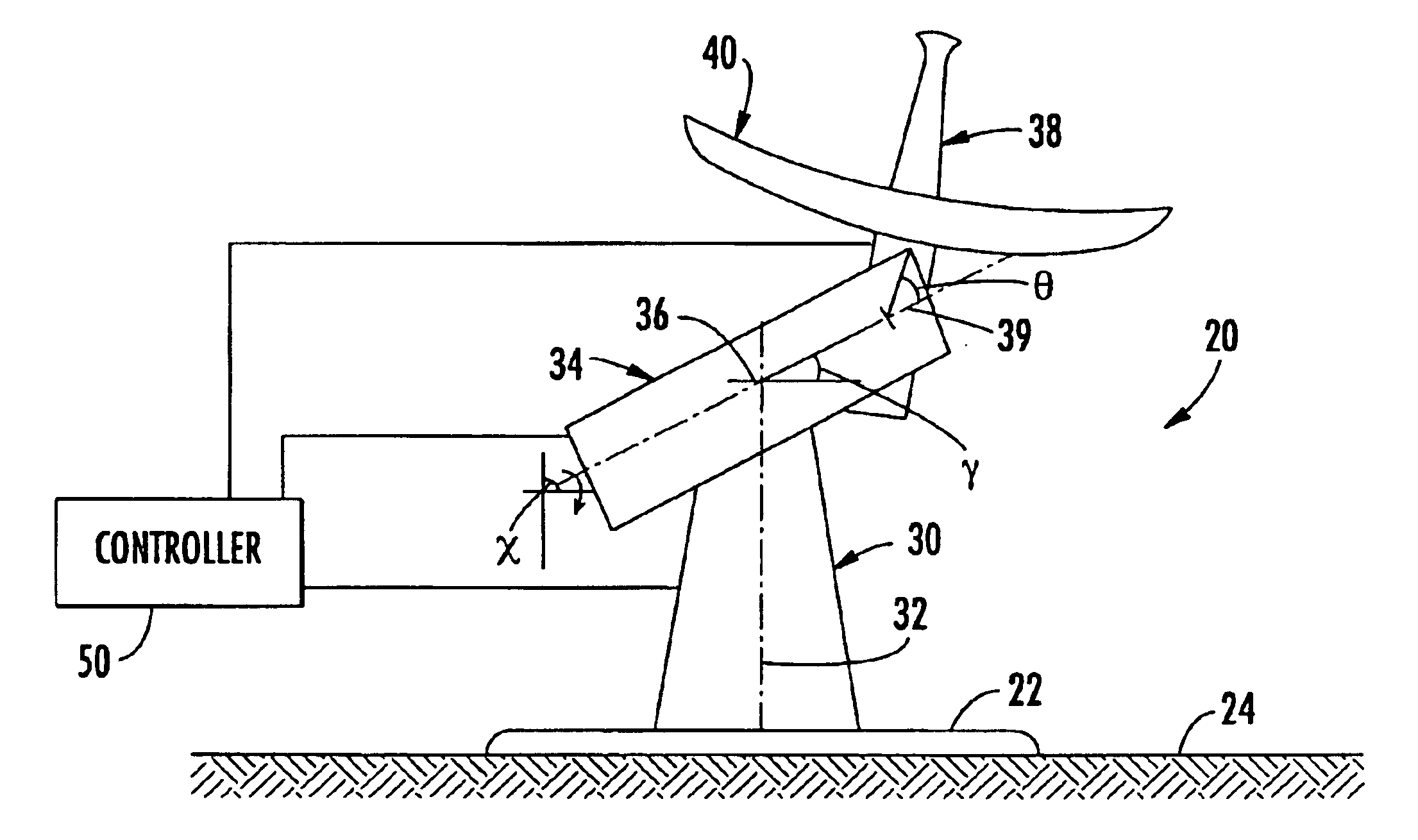
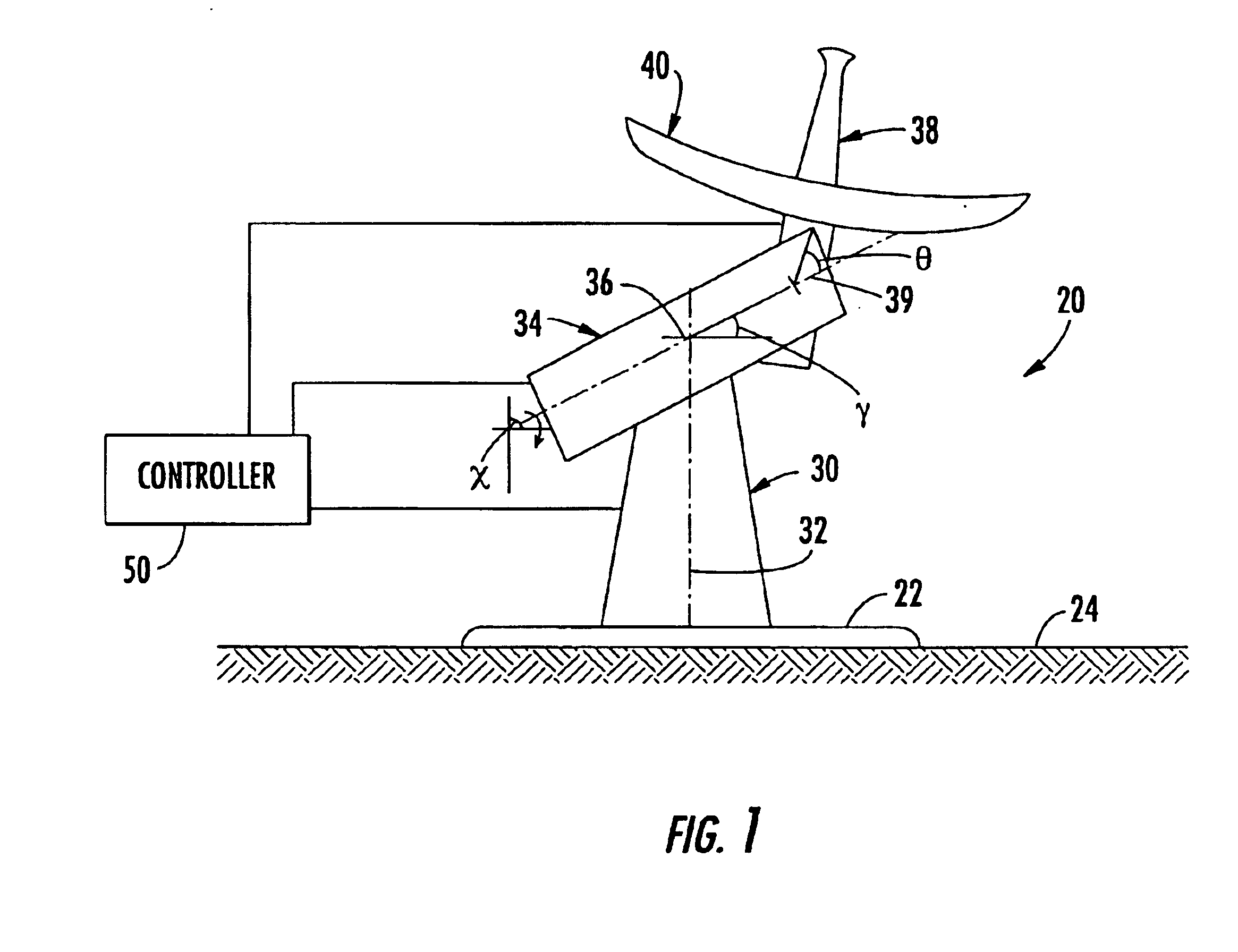
Referring initially to FIGS. 1-2, an antenna assembly 20 for operation on a moving platform 24 is now described. The antenna assembly 20 illustratively includes a base 22 mounted to a moving platform 24. The moving platform 24 may, for example, be a deck of a ship at sea, a buoy, a land vehicle traveling across terrain, or any other moving platform as understood b...


PUM


Abstract

An antenna assembly for operation on a moving platform includes a base to be mounted on the moving platform, an azimuthal positioner extending upwardly from the base, and a canted cross-level positioner extending from the azimuthal positioner at a cross-level cant angle canted from perpendicular. The canted cross-level positioner may be rotatable about a cross-level axis to define a roll angle resulting in coupling between the azimuthal and canted cross-level positioners. The antenna assembly may also include an elevational positioner connected to the canted cross-level positioner resulting in coupling between the elevational and the azimuthal positioners because of the roll angle. An antenna may be connected to the elevational positioner. A controller operates the azimuthal, canted cross-level, and elevational positioners to aim the antenna along a desired line-of-sight and while decoupling at least one of the azimuthal and canted cross-level positioners, and the azimuthal and elevational positioners.

Description

FIELD OF THE INVENTIONThe present invention relates to the field of antennas, and, more specifically, to the field of antenna positioner control systems, and related methods.BACKGROUND OF THE INVENTIONAn antenna stabilization system is generally used when mounting an antenna on an object that is subject to pitch and roll motions, such as a ship at sea, a ground vehicle, an airplane, or a buoy, for example. It is desirable to maintain a line-of-sight between the antenna and a satellite, for example, to which it is pointed. The pointing direction of an antenna mounted on a ship at sea, for example, is subject to rotary movement of the ship caused by changes in the ship's heading, as well as to the pitch and roll motion caused by movement of the sea.U.S. Pat. No. 4,156,241 to Mobley et al. discloses a satellite antenna mounted on a platform on a surface of a ship. The antenna is stabilized and decoupled from motion of the ship using sensors mounted on the platform. U.S. Pat. No. 5,769,...

Claims


Application Information

Patent Timeline
Patent Type & Authority Patents(United States)
IPC IPC(8): H01Q3/08
CPCH01Q3/08
Inventor ROYALTY, JAMES MALCOLM BRUCE
Owner NORTH SOUTH HLDG
Why Eureka
Try Eureka