AI technical title is built by Patsnap AI team. It summarizes the technical point description of the patent document.
a coding method and image technology, applied in the field of image predictive coding apparatus and methods, image predictive decoding apparatus and methods and recording media, can solve the problems of insufficient consideration of intra-frame coding, inability to use actual methods to remove redundancy between blocks, and restricted to the inside, so as to achieve high accuracy and speed.
Inactive Publication Date: 2005-02-22
SUN PATENT TRUST
View PDF22 Cites 58 Cited by
Summary
Abstract
Description
Claims
Application Information
AI Technical Summary
This helps you quickly interpret patents by identifying the three key elements:
Problems solved by technology
Method used
Benefits of technology
Benefits of technology
This approach significantly improves coding efficiency by reducing the number of bits required for encoding, enhancing image quality by effectively addressing both spatial and inter-block redundancies, and simplifying the prediction signalgeneration process.
Problems solved by technology
However, the fact that no actual method uses a process for removing the redundancy between blocks of an image is apparent from the above description.
According to the existing image coding techniques, the DCT transform process or other transform process is executed on the block basis due to the restrictive conditions in terms of hardware formation and calculation.
However, it is restricted to the inside of a block.
In particular, the intra-frame coding which consistently consumes a great amount of bits is not satisfactorily considered.
Method used
Image
Click on the blue label to locate the original text in one second.
Reading with bidirectional positioning of images and text.
Examples
first preferred embodiment group
The first preferred embodiment group includes first through fourth preferred embodiments.
first preferred embodiment
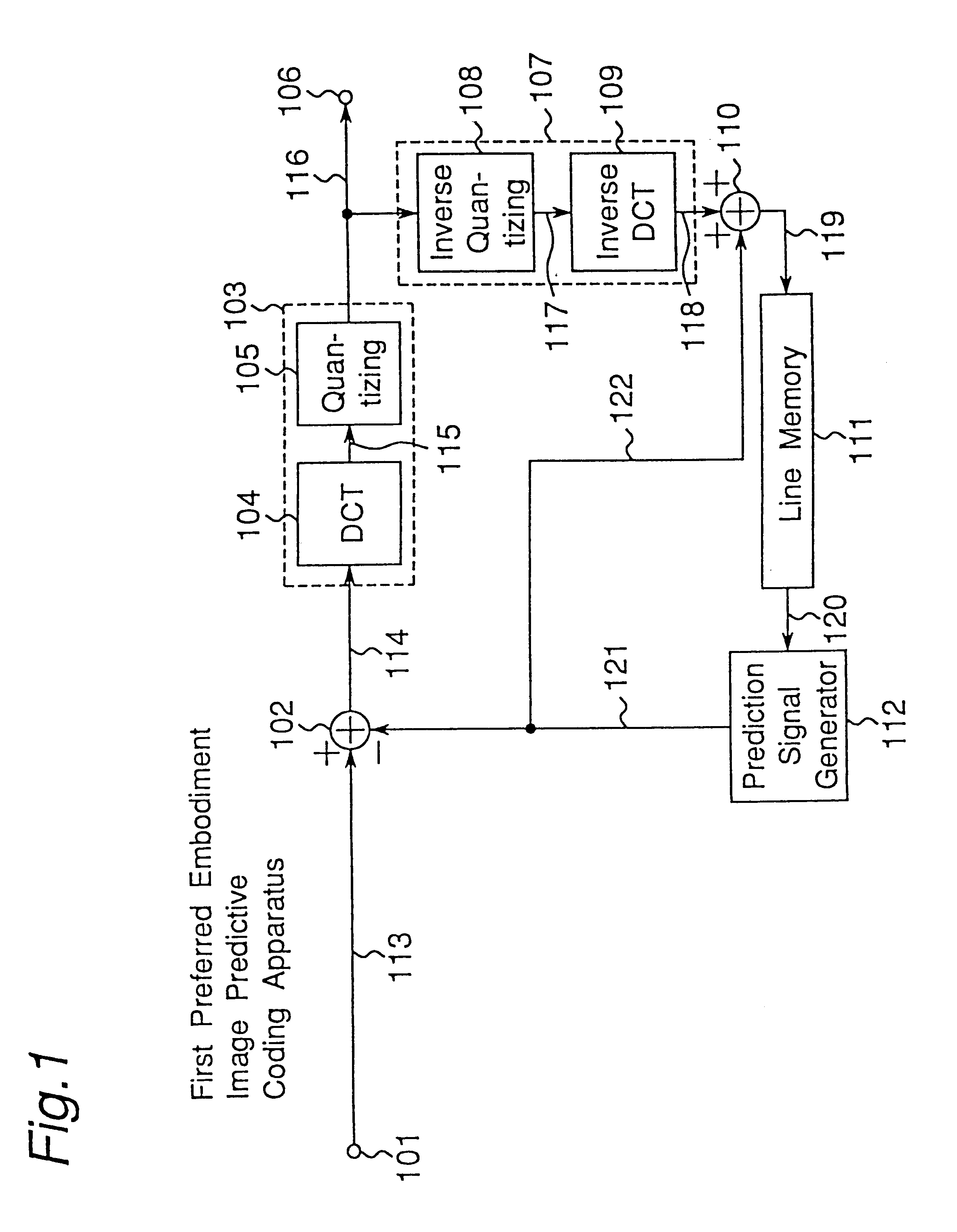
FIG. 1 is a block diagram showing a construction of an image predictive coding apparatus according to a first preferred embodiment of the present invention.
In FIG. 1 are shown an input terminal 101, a first adder 102, an encoder 103, an output terminal 106, a decoder 107, a second adder 110, a line memory 111 and a prediction signal generator 112.
The construction and operation of the image predictive coding apparatus will be described below. Objective image data to be subjected to a coding process is inputted to the input terminal 101. In this case, the inputted image data is divided into a plurality of adjacent small regions.
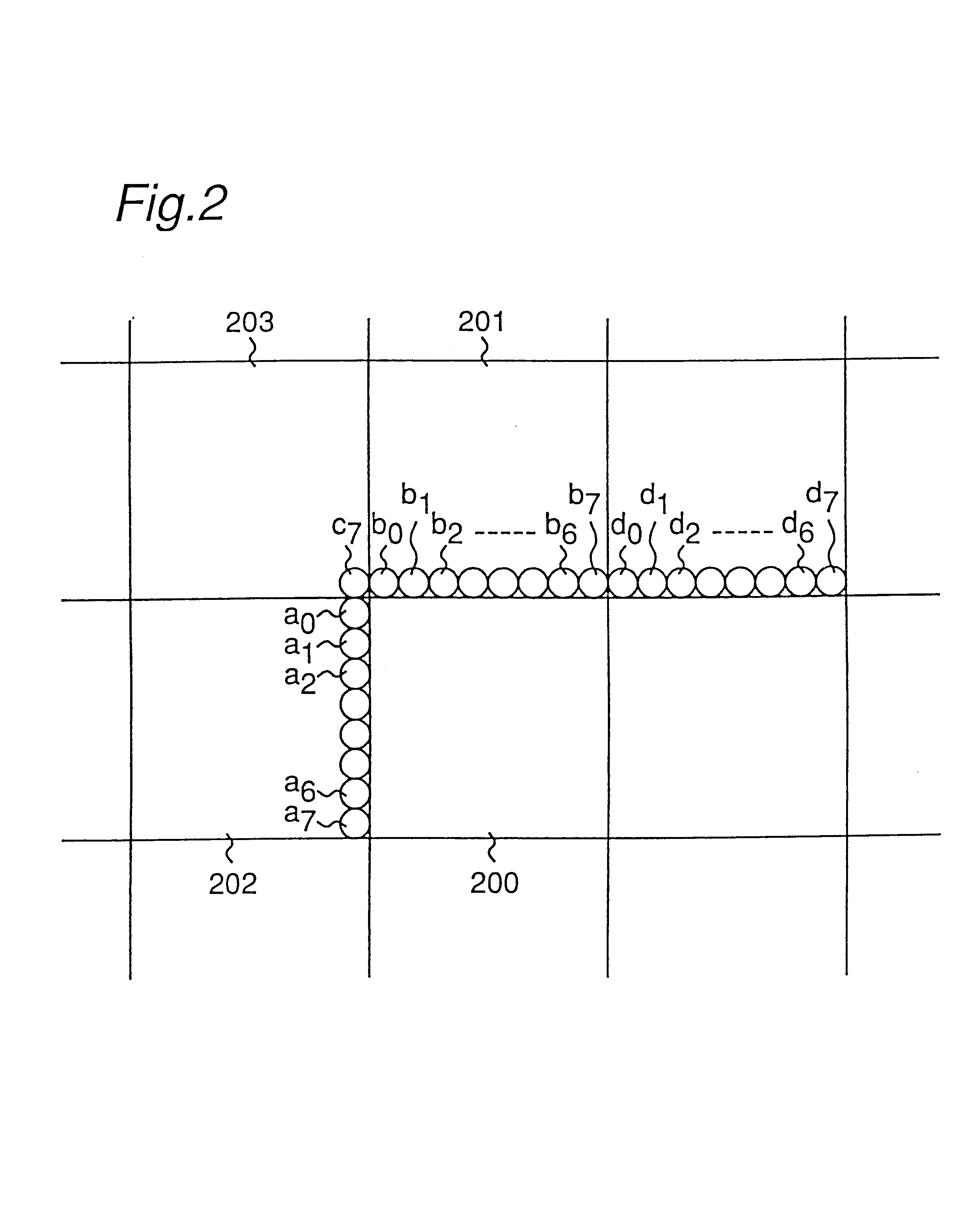
FIG. 2 shows the image of the inputted image data in a case where it is divided into small regions of 8×8 samples. FIG. 3 shows the image of the inputted image data in a case where it is divided into triangular small regions. The image data of the plurality of small regions are successively coded when the image data of the objective small region to be processed...
second preferred embodiment
FIG. 8 is a block diagram showing a construction of an image predictive coding apparatus according to a second preferred embodiment of the present invention, where the components similar to those of FIG. 1 are denoted by the same reference numerals.
The image predictive coding apparatus shown in FIG. 8 is characterized in that a motion detector 700, a motion compensator 701, an optimum mode selector 703 and a frame memory 702 are incorporated into the image predictive coding apparatus of FIG. 1.
The construction and operation of the image predictive coding apparatus of FIG. 8 will be described below.
In a manner similar to that of the first preferred embodiment, inputted image data of the target small region to be processed is inputted via an input terminal 101 to an adder 102. The adder 102 subtracts the image data of the target small region to be processed from image data of an optimum prediction small region inputted from an optimum mode selector 703 via a line 121 and thereafter ou...
PUM
Abstract
There is disclosed image predictive coding apparatus and method, image predictive decoding apparatus and method, and recording medium which stores therein the image predictive coding method or the image predictive decoding method, of which the transform efficiency is remarkably improved in comparison with the prior art. According to the image predictive coding apparatus and method, when dividing inputted image data to be coded into image data of a plurality of small regions which are adjacent to each other and coding the image data of an objective small region to be processed among the image data of the plurality of divided small regions which are adjacent to each other, reconstructed image data of a reproduction small region adjacent to the image data of the objective small region to be processed is used as image data of an intra-frame prediction small region of the objective small region to be processed, the image data of the intra-frame prediction small region is used as image data of an optimum prediction small region and image data of a difference small region which are differences between the image data of the objective small region to be processed and the image data of the optimum prediction small region is generated. Then, the generated image data of the difference small region is coded and outputted, and then the coded image data of the difference small region is decoded, so that the reconstructed image data of the reproduction small region is generated by adding the decoded image data of the difference small region to the image data of the optimum prediction small region.
Description
TECHNICAL FIELDThe present invention relates to an image predictive coding apparatus and method, image predictive decoding apparatus and method and recording medium. The present invention relates, in particular, to an image predictive coding apparatus and method as well as image predictive decoding apparatus and method for storing digital image data of an image which is a static image or a dynamic image into a recording medium such as an optical disk or for transmitting the data through a communication line. The present invention also relates to a recording medium in which a program including the steps of the image predictive coding method is recorded as well as a recording medium in which a program including the steps of the image predictive decoding method is recorded.BACKGROUND ARTFor the purpose of efficiently storing or transmitting a digital image, the image is required to be coded in a compression coding manner. As a method for coding a digital image in a compression coding m...
Claims
Application Information
Patent Timeline
Application Date:The date an application was filed.
Publication Date:The date a patent or application was officially published.
First Publication Date:The earliest publication date of a patent with the same application number.
Issue Date:Publication date of the patent grant document.
PCT Entry Date:The Entry date of PCT National Phase.
Estimated Expiry Date:The statutory expiry date of a patent right according to the Patent Law, and it is the longest term of protection that the patent right can achieve without the termination of the patent right due to other reasons(Term extension factor has been taken into account ).
Invalid Date:Actual expiry date is based on effective date or publication date of legal transaction data of invalid patent.

