Optical fiber, optical fiber cable, and radiation detecting system using such

a radiation detection and optical fiber technology, applied in the direction of radiation particle tracking, optical fibre, instruments, etc., can solve the problems of large cost to construct such a monitoring system, inability to adequately locate the monitoring apparatus at all of the required areas, and serious damage to the human body, etc., to achieve the effect of low cost and low cos

Inactive Publication Date: 2005-02-22
WIRED JAPAN
View PDF11 Cites 15 Cited by
  • Summary
  • Abstract
  • Description
  • Claims
  • Application Information

AI Technical Summary

Benefits of technology

The present invention has been developed in view of aforementioned circumstances. One object of the present invention is to provide an optical fiber and an optical fiber cable at a low cost. Another object of the present invention is to provide a radiation detecting system for detecting the radiation leak at a low cost.

Problems solved by technology

In facilities where radiation is handled or utilized, radiation leak causes a serious damage to human body.
Since such conventional radiation-monitoring system presupposes to locate the scintillometer at each detection area and additionally the scintillometer is expensive, significant cost is necessary to construct such monitoring system.
Under the circumstance usually having budget control, it may happen that the monitoring apparatuses cannot adequately be located at all of required areas.

Method used


Image

  • Optical fiber, optical fiber cable, and radiation detecting system using such
  • Optical fiber, optical fiber cable, and radiation detecting system using such
  • Optical fiber, optical fiber cable, and radiation detecting system using such

Examples


Embodiment Construction

Preferable embodiments provided with an optical fiber, an optical fiber cable, and a radiation detecting system according to the present invention will be described in detail thereinafter.

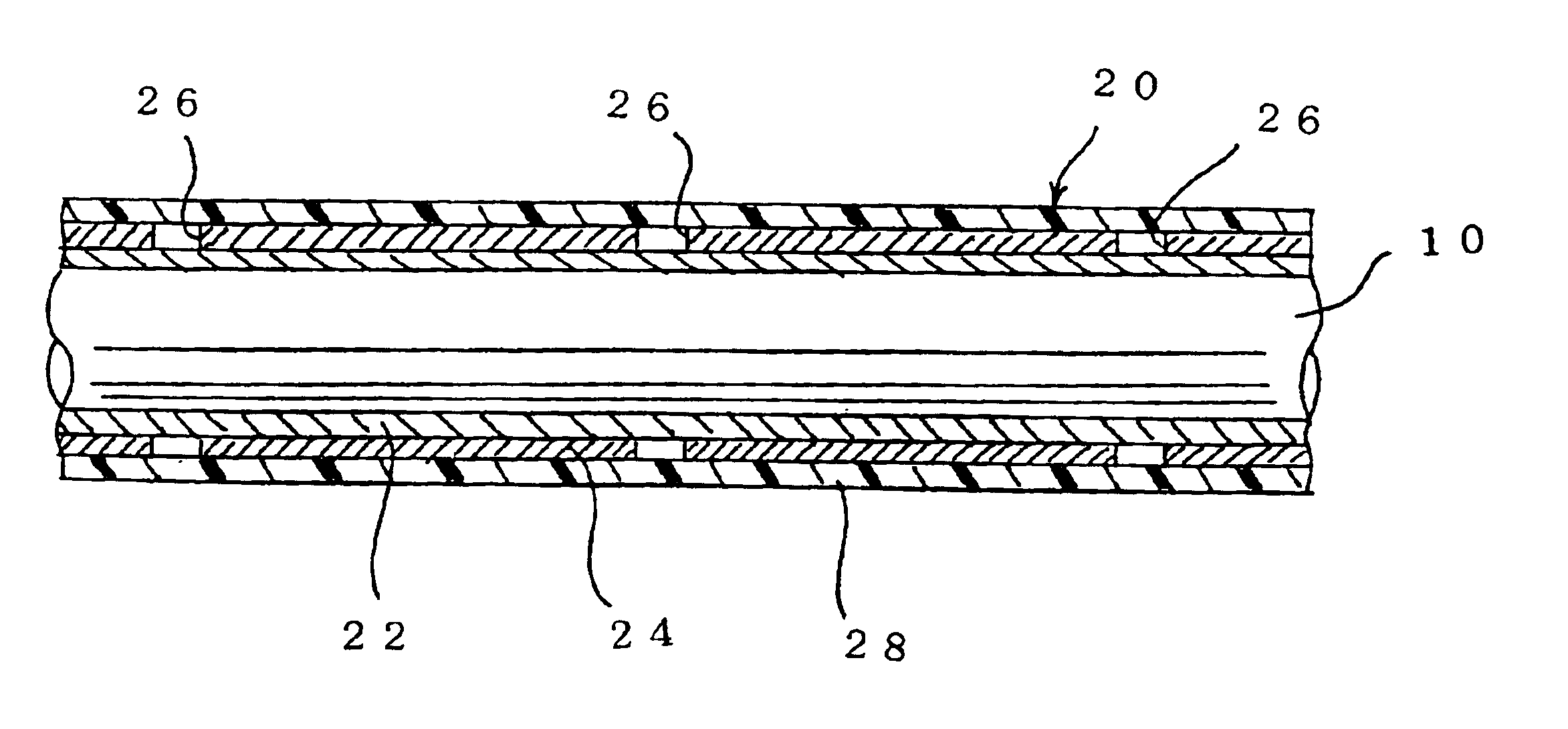
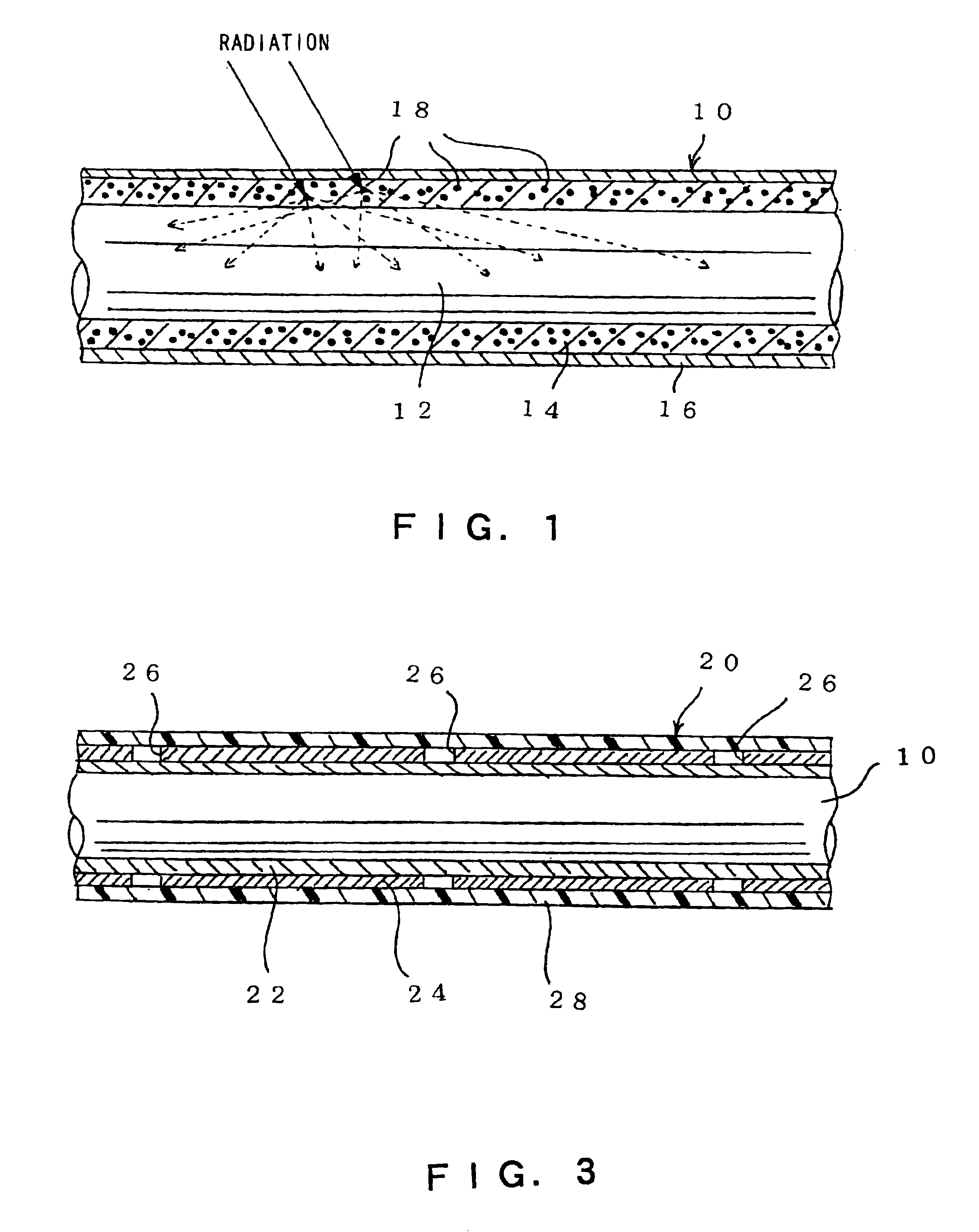
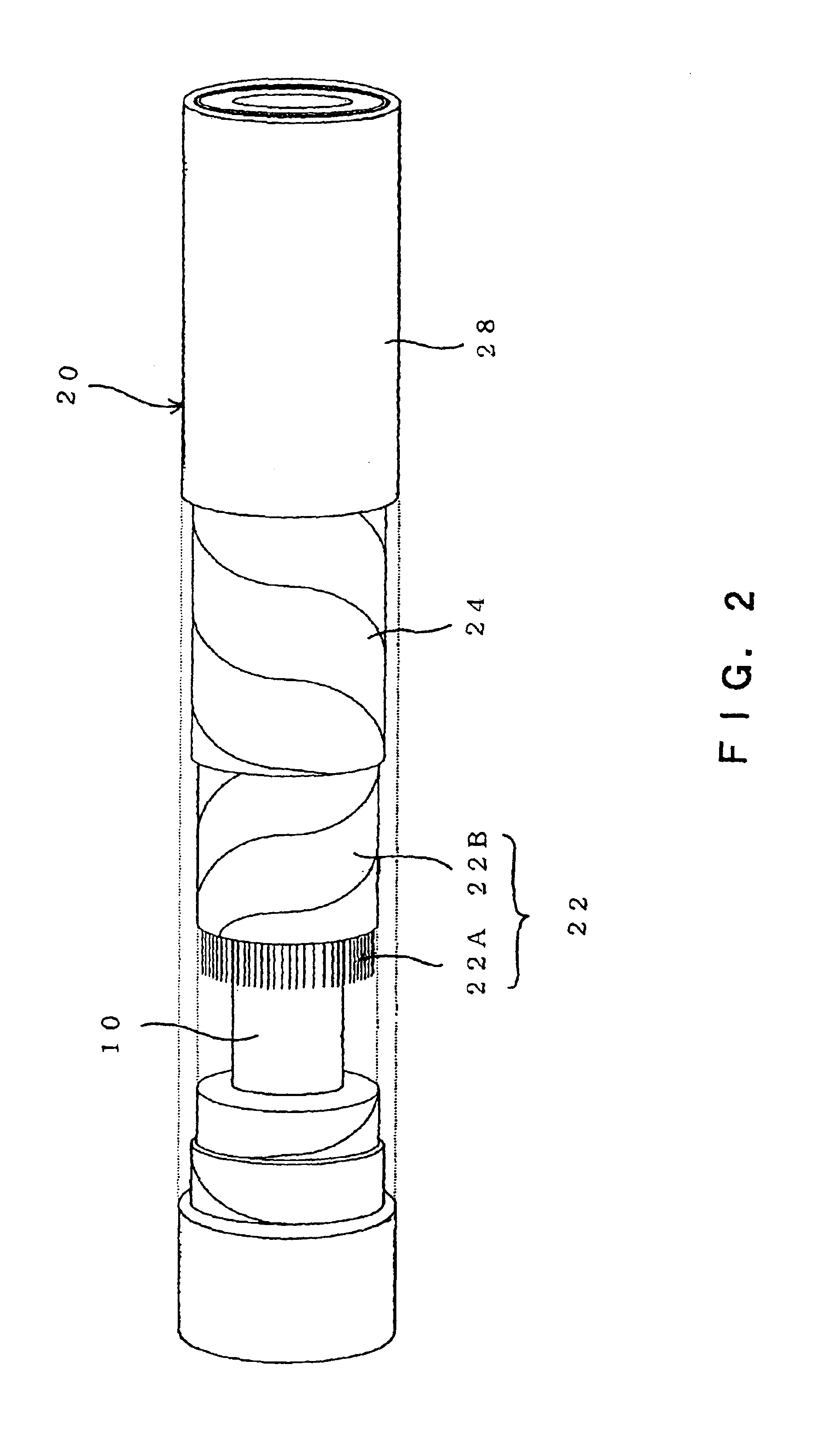
First of all, the optical fiber and the optical fiber cable are described with reference to FIG. 1 though FIG. 3. As shown in FIG. 1, an optical fiber 10 according to this embodiment is generally composed of a core 12 made of solid quartz glass, having lightwave guide property and extending along one direction, a clad layer 14 covering over a peripheral surface of the core 12 with appressed thereto, and a protective layer 16 protecting the clad layer 14 with covering over a peripheral surface of the clad layer 14. As is conventional, the fiber is flexible.

Here the description of the core 12, which is of well-known configuration, is abbreviated. However, it is apparent that the core 14 is not limited to be solid quartz glass and it may be made of transparent plastic material.

As material of the afore...


PUM


Abstract

The present invention provides an optical fiber, an optical fiber cable and a radiation detecting system at a low cost. Further, the radiation detecting system is provided which can adequately monitor the radiation leak without delay. The optical fiber cable comprises: an optical fiber including; a core 12 having lightwave guide property and extending along one direction; a clad layer 14 covering over a peripheral surface of the core 12; and a scintillator material dispersed in the clad layer 14 and emitting light when radiation is applied, a radiation-shielding layer 24 covering substantially over a periphery of the optical fiber10, and a gap 26 located in at least one part of the radiation-shielding layer 24. The radiation detecting system comprises an optical fiber cable 20 adapted to emit light at a region where radiation is applied and transmitting the emitted light, photoelectric conversion means 32 connected to at least one end of the optical fiber cable 20, and processing means 38 detecting when radiation is applied in accordance with an output signal of the photoelectric conversion means 32.

Description

BACKGROUND OF THE INVENTION1. Field of the InventionThe present invention relates to an optical fiber and an optical fiber cable interiorly providing such an optical fiber. Further the present invention relates to a radiation detecting system for monitoring radiation leak, using such an optical fiber and an optical fiber cable.2. Prior ArtIn facilities where radiation is handled or utilized, radiation leak causes a serious damage to human body. Thus various measures are taken in bar of these matter. In the unlikely event that the radiation leak occurs, some detecting system for quickly and reliably detecting this has been developed and has also come into practical use.For example, a monitoring system, in which radiation-monitoring apparatuses such as well-known scintillometers are located at all of areas where the radiation leak potentially occurs to monitor the radiation leak all the time, has been established and used.Since such conventional radiation-monitoring system presupposes...

Claims


Application Information

Patent Timeline
Patent Type & Authority Patents(United States)
IPC IPC(8): G02B6/036G02B6/02G02B6/44G01T1/20G01T5/08
CPCG01T1/20G01T1/201G02B6/03694G02B6/4432G02B6/02033G02B6/02395
Inventor SUGIHARA, HIROSHI
Owner WIRED JAPAN
Why Eureka
Try Eureka