
Toner refilling device and developing device using the same for an image forming apparatus

Inactive Publication Date: 2005-02-22
RICOH KK
View PDF29 Cites 63 Cited by
  • Summary
  • Abstract
  • Description
  • Claims
  • Application Information

AI Technical Summary

Benefits of technology

It is an object of the present invention to provide a developing device capable of being rapidly refilled with a developer to thereby obviate an increase in cost and the interruption of image formation ascribable to frequent replacement, and an image forming apparatus using the same.
It is another object of the present invention to provide a toner refilling device configured to prevent a service person from putting the wrong toner container in an image forming apparatus or refilling a toner container with the wrong toner, and image forming apparatus using the same.

Problems solved by technology

However, discarding the empty toner container is not desirable from the environment and resource standpoint.
However, the problem with the conventional recycling methods is that the empty toner container must be collected from the user's station, transported to a recycling factory, and then refilled with fresh toner.
Such a procedure increases the recycling cost and time and is therefore undesirable for both of the user and manufacturer.
It follows that an increase in the amount of toner to store directly translates into an increase in the size of the toner container and therefore in a space necessary for accommodating it.
This increases the size of the developing device and therefore the overall size of the image forming apparatus including it.
When the toner container is reduced in size to prevent the size of the image forming apparatus from increasing, the toner container must be frequently replaced when toner is consumed at a high rate, resulting in an increase in running cost.
Moreover, when the toner cartridge is collected from the user's station and then refilled, the recycling cost and time are increased, as stated earlier.
However, the toner refilling device stated above has a problem that a service person is apt to take one toner container for another toner container or one toner for another toner during the refilling operation performed at the user's station.
The problem stated above is likely to occur not only at the user's station but also at, e.g., a service company where the system for controlling the refilling procedure is not so strict as in a factory.

Method used


Image

  • Toner refilling device and developing device using the same for an image forming apparatus
  • Toner refilling device and developing device using the same for an image forming apparatus
  • Toner refilling device and developing device using the same for an image forming apparatus

Examples


first embodiment

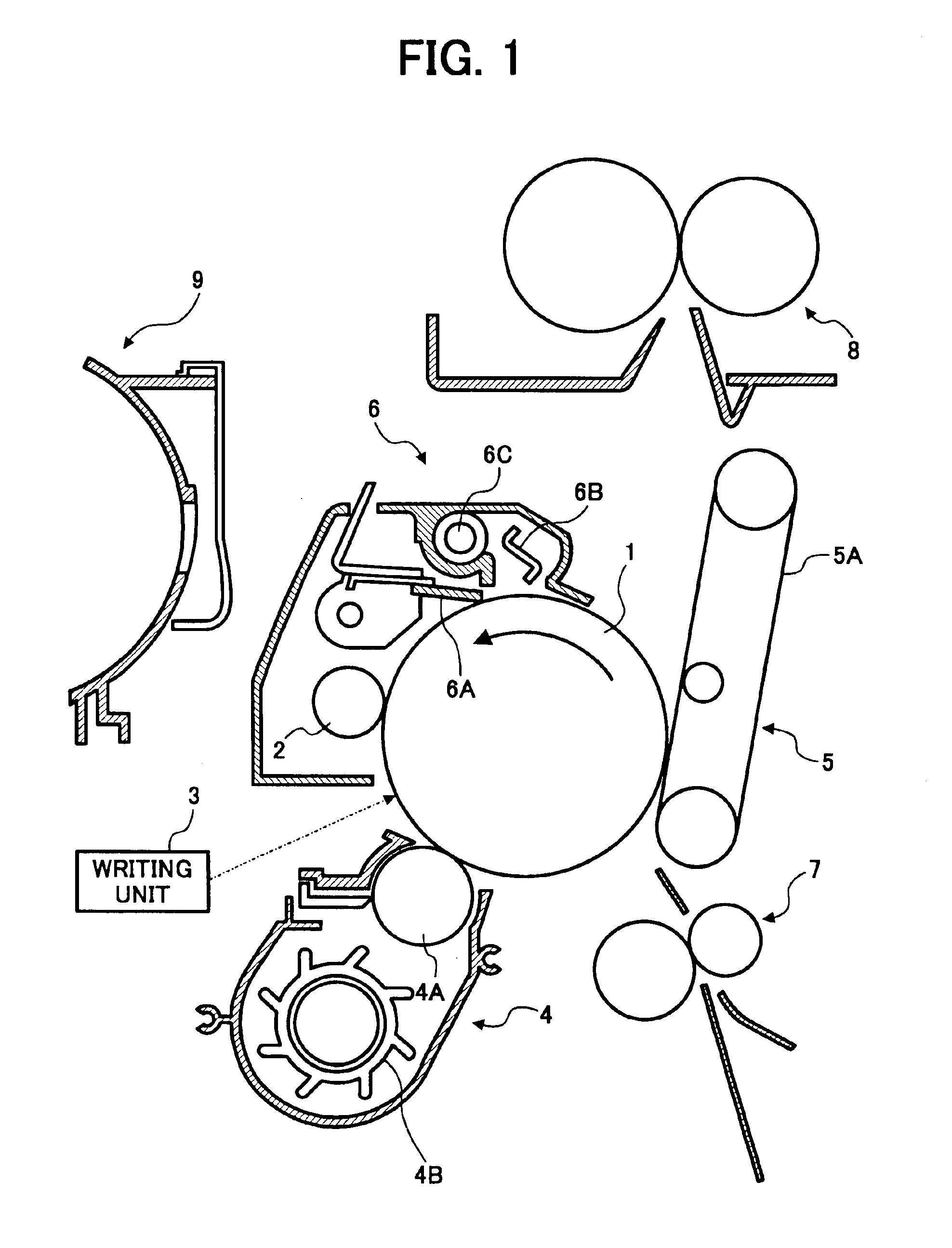
Referring to FIG. 1 of the drawings, an image forming apparatus to which a developing device embodying the present invention is applied is shown. The image forming apparatus is implemented as a printer of the type forming a latent image on an image carrier in accordance with image data although it may, of course, be implemented as, e.g., a copier or a facsimile apparatus.

As shown in FIG. 1, the printer includes a photoconductive drum or image carrier 1 rotatable in a direction indicated by an arrow. Arranged around the drum 1 are a charge roller or charging device 2, an optical writing unit 3, a developing device 4, an image transferring device 5, and a cleaning device 6. The charge roller 2 uniformly charges the surface of the drum 1 being rotated. The optical writing unit 3 scans the charged surface of the drum 1 with a light beam in accordance with image data, thereby forming a latent image on the drum 1. The developing device 4 develops the latent image with toner to thereby pro...

second embodiment

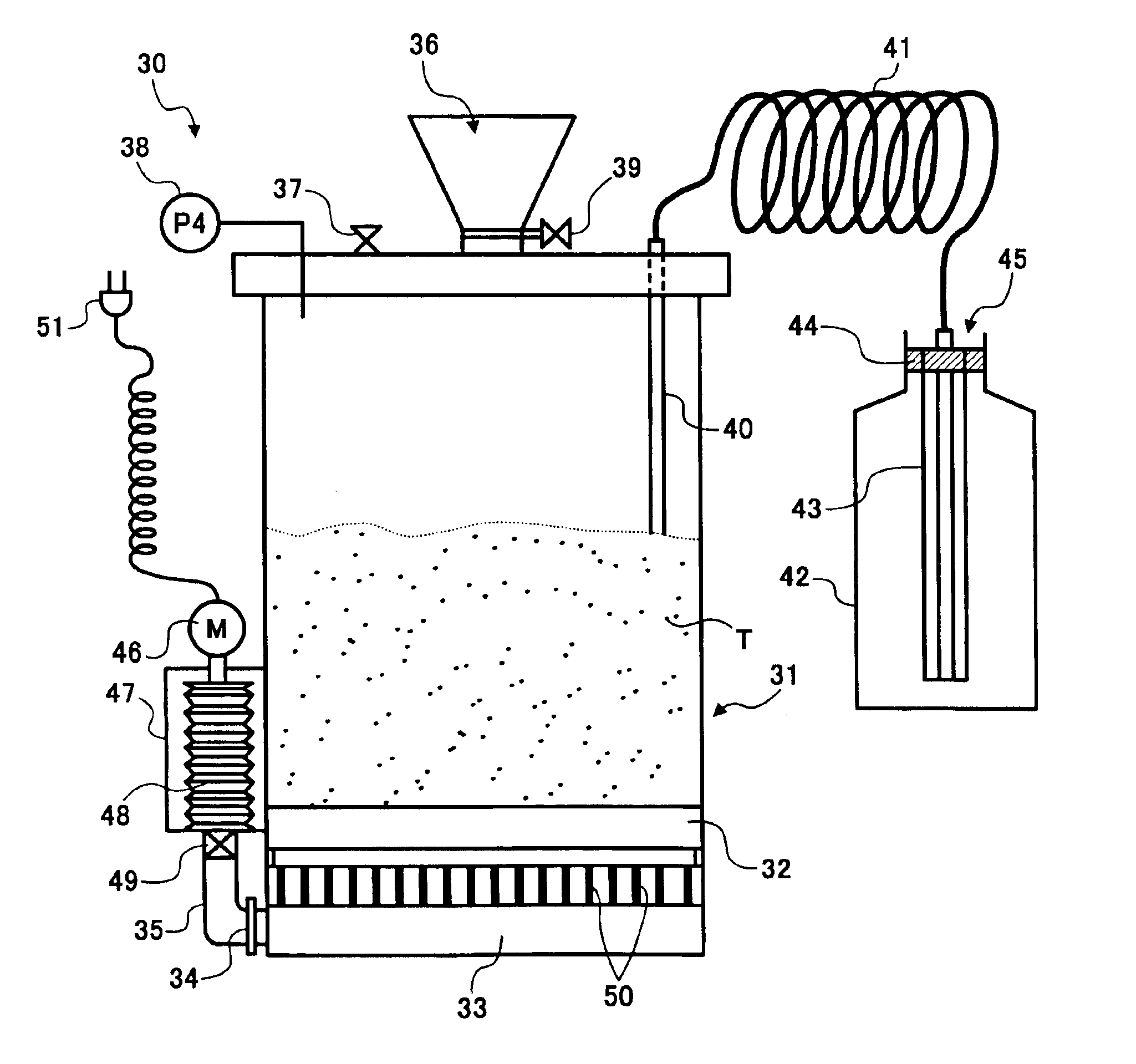
Referring to FIG. 19, an alternative embodiment of the present invention is shown and also provided with a portable configuration. As shown, the toner refilling device, generally 30, includes a toner fluidizing device 31 which is usually hermetically closed. A porous plate 32 is removably mounted on the bottom portion of the fluidizing device 31 via a flange, not shown, for causing toner to flow. The porous plate 32 is implemented as, e.g., a sintered metal plate, a baked resin plate or a mesh screen with a small mesh. An air header 33 is positioned beneath the porous plate 32 while a pipe 35 is removably fitted in the air header 33 and provided with a control valve 34.

A hopper 36 is positioned on the top of the fluidizing device 31 for allowing fresh toner T to be introduced into the fluidizing device 31. A valve 37 is operated to depressurize the inside of the fluidizing device 31. A pressure gauge 38 is responsive to pressure inside the fluidizing device 31. A flow rate control v...


PUM


Abstract

In a developing device of the present invention for depositing toner on an image carrier to thereby develop a latent image formed thereon, a toner refilling device is configured to refill, when the toner is short, fresh toner at a position where the developing device is situated.

Description

BACKGROUND OF THE INVENTION1. Field of the InventionThe present invention relates to a copier, facsimile apparatus, printer or similar image forming apparatus for forming a toner image on an image carrier with toner fed from a toner container. Mote particularly, to a toner refilling device for refilling fresh toner in a toner container run out of toner and a developing device using the same.2. Description of the Background ArtIt is a common practice with an image forming apparatus to form a latent image on a photoconductive element or image carrier and develop the latent image with toner or similar developer. The toner, which has critical influence on image density, is consumed due to repeated development, so that fresh toner must be replenished, as needed.An image forming apparatus of the type using a toner cartridge, toner bottle, toner hopper or similar toner container is conventional. In this type of apparatus, when the toner container runs out of toner due to consumption, it is...

Claims


Application Information

Patent Timeline
IPC IPC(8): G03G15/00G03G15/08
CPCG03G15/0863G03G15/0855G03G15/0865G03G15/0872G03G2215/0697
Inventor ITOH, FUMIHITOKATOH, SHUNJIAMANO, HIROSATOMAKINO, KUNIOENOMOTO, TAKAMICHIUEMURA, HIROYUKI
Owner RICOH KK
Learn More