Aircraft defueling system

a defueling system and aircraft technology, applied in the field of aircraft equipment, can solve the problems of fuels below the lfl/lel that are considered too lean to burn, fuels and fuels that are considered too rich to burn

Active Publication Date: 2005-03-01
SPOKANE STAINLESS TECH INC
View PDF5 Cites 32 Cited by
  • Summary
  • Abstract
  • Description
  • Claims
  • Application Information

AI Technical Summary

Benefits of technology

According to some embodiments, there may be multiple defueling hoses and additional vacuum generators. Further, some embodiments include a telescoping funnel that can be selectively isolated from the vacuum fuel tank so that the tank can be held at vacuum pressure.

Problems solved by technology

One of the most commonly recognized difficulties associated with airplanes and other aircraft is fueling and defueling.
Fuels below the LFL / LEL are considered too lean to burn.
If the fuel vapor concentration exceeds the upper flammability limit or upper explosive limit, the fuel is considered too rich to burn.
In addition, hydrocarbons, including jet fuel, may also present toxic or irritant hazards.
At high concentrations, jet fuel and other hydrocarbons can affect the nervous system, causing headache, dizziness, and lack of coordination.
Exposure to some hydrocarbons may also cause skin irritations if not controlled.
However, most defueling systems include gravity draining, resulting in low flow rates and long drain times. In fact, for many large airplanes, depending on the amount of fuel remaining in the tanks, it can take up to seven hours or more to fully drain the fuel from the plane using a gravity dependent system.
However, if the main vacuum is lost, the seal of the coupler is also compromised, and fuel can potentially leak.

Method used


Image

  • Aircraft defueling system
  • Aircraft defueling system
  • Aircraft defueling system

Examples


Embodiment Construction

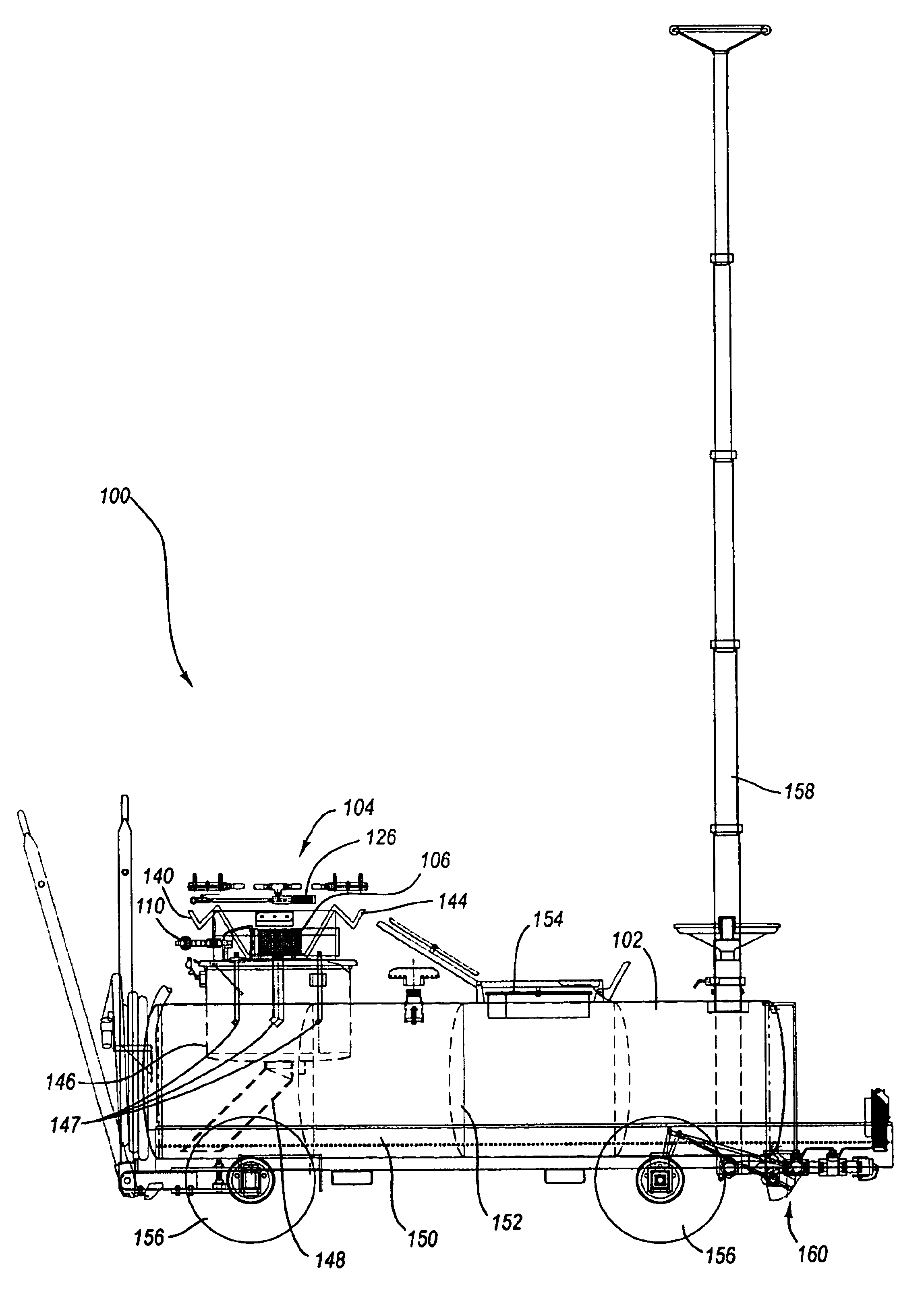
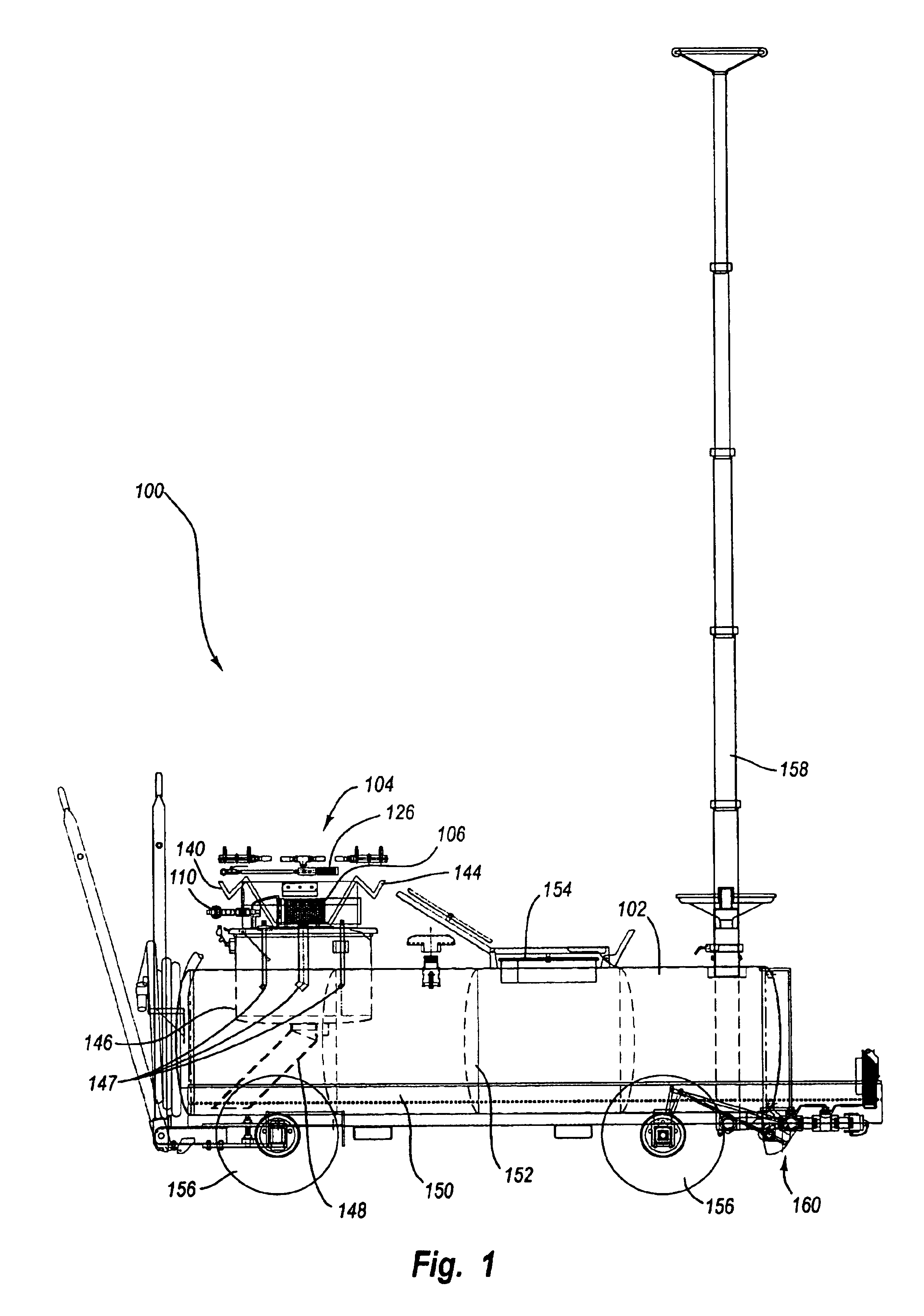
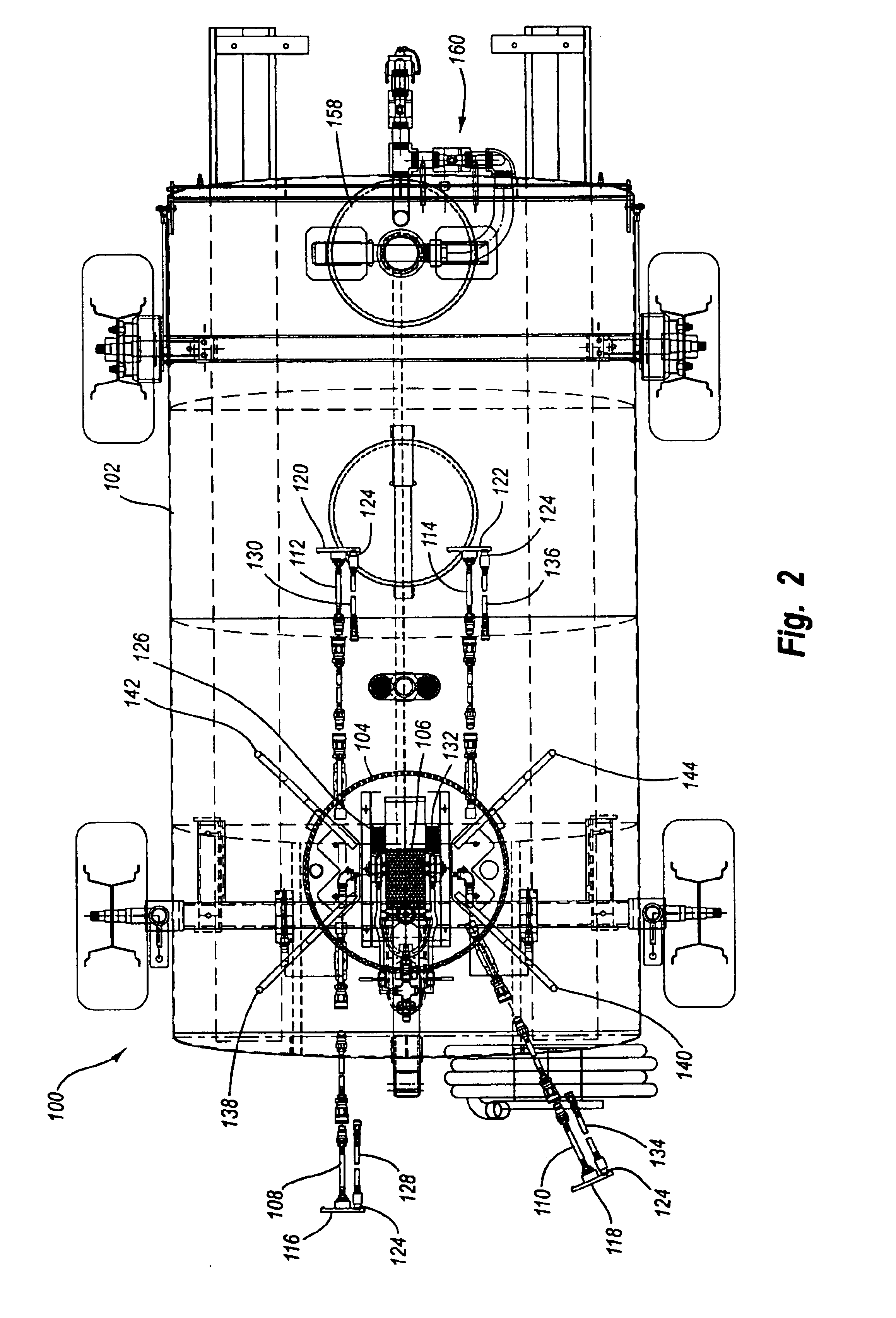
It is a common procedure to defuel an aircraft prior to storage, maintenance, or repair. Most aircraft include one or more drain valves at low points of the fuel tanks to facilitate defueling. The drain valves are usually spring loaded “poppet” valves that are opened by the application of a force normal to the spring force. There are a number of devices available for defueling aircraft, which are often generally referred to as “bowsers.” Some aircraft defuelers include telescopic funnels that provide the defueler with an extended reach. The extended reach telescopic funnel facilitates defueling from drain valves that are located in particularly high places on some aircraft.

However, telescopic funnels are generally limited to direct gravity draining, which often results in a very long defueling interval. Further, previous telescopic funnel assemblies are open to and in constant fluid communication with the defueling tank. Therefore, previous aircraft defuelers are not capable of main...


PUM

PropertyMeasurementUnit
suctionaaaaaaaaaa
vacuumaaaaaaaaaa
pressureaaaaaaaaaa

Abstract

An apparatus and method for defueling and aircraft. The apparatus includes a vacuum fuel tank comprising a first vacuum generator, a defueling hose in fluid communication with the vacuum fuel tank, a first defueling fitting attached to the first defueling hose, and a second vacuum generator operatively connected to the first defueling fitting. By providing both a first and a second vacuum generator, the defueling fitting can be attached and detached from an aircraft independent of the suction used to withdraw fuel from an aircraft. According to some embodiments, there may be multiple defueling hoses and additional vacuum generators. Further, some embodiments include a telescoping funnel that can be selectively isolated from the vacuum fuel tank so that the tank can be held at vacuum pressure.

Description

FIELD OF THE INVENTIONThe present invention relates to aircraft equipment, and more particularly to an aircraft defueling system.BACKGROUND OF THE INVENTIONOne of the most commonly recognized difficulties associated with airplanes and other aircraft is fueling and defueling. Jet fuel, for example, is a flammable hydrocarbon liquid that can be ignited even in certain ambient conditions, primarily based on temperature and vapor concentration. The temperature at which the vapors of a flammable liquid can ignite is known as the “flash point.” A hazardous vapor concentration is present when a fuel vapor reaches a level known as the lower flammability limit (LFL) or lower explosive limit (LEL). These limits are usually expressed as a percentage by volume. Fuels below the LFL / LEL are considered too lean to burn. If the fuel vapor concentration exceeds the upper flammability limit or upper explosive limit, the fuel is considered too rich to burn. A fuel vapor concentration between these two...

Claims


Application Information

Patent Timeline
Patent Type & Authority Patents(United States)
IPC IPC(8): B64F1/28B64F1/00
CPCB64F1/28
Inventor KUNTZ, JAMES P.
Owner SPOKANE STAINLESS TECH INC
Why Eureka
Try Eureka