Front folding agricultural implement

a technology for agricultural implements and folding machines, applied in agricultural tools and machines, agricultural machines, adjusting devices, etc., can solve the problems of unnecessarily and achieve the effect of reducing increasing the overall width of the folded machin

a technology for agricultural implements and folding machines, applied in agricultural tools and machines, agricultural machines, adjusting devices, etc., can solve the problems of unnecessarily and achieve the effect of reducing increasing the overall width of the folded machin

US6860335B2Inactive Publication Date: 2005-03-01GREAT PLAINS MFG INC

Image

  • Front folding agricultural implement
  • Front folding agricultural implement
  • Front folding agricultural implement

Examples


Embodiment Construction

The present invention is susceptible of embodiment in many different forms. While the drawings illustrate and the specification describes certain preferred embodiments of the invention, it is to be understood that such disclosure is by way of example only. There is no intent to limit the principles of the present invention to the particular disclosed embodiments.

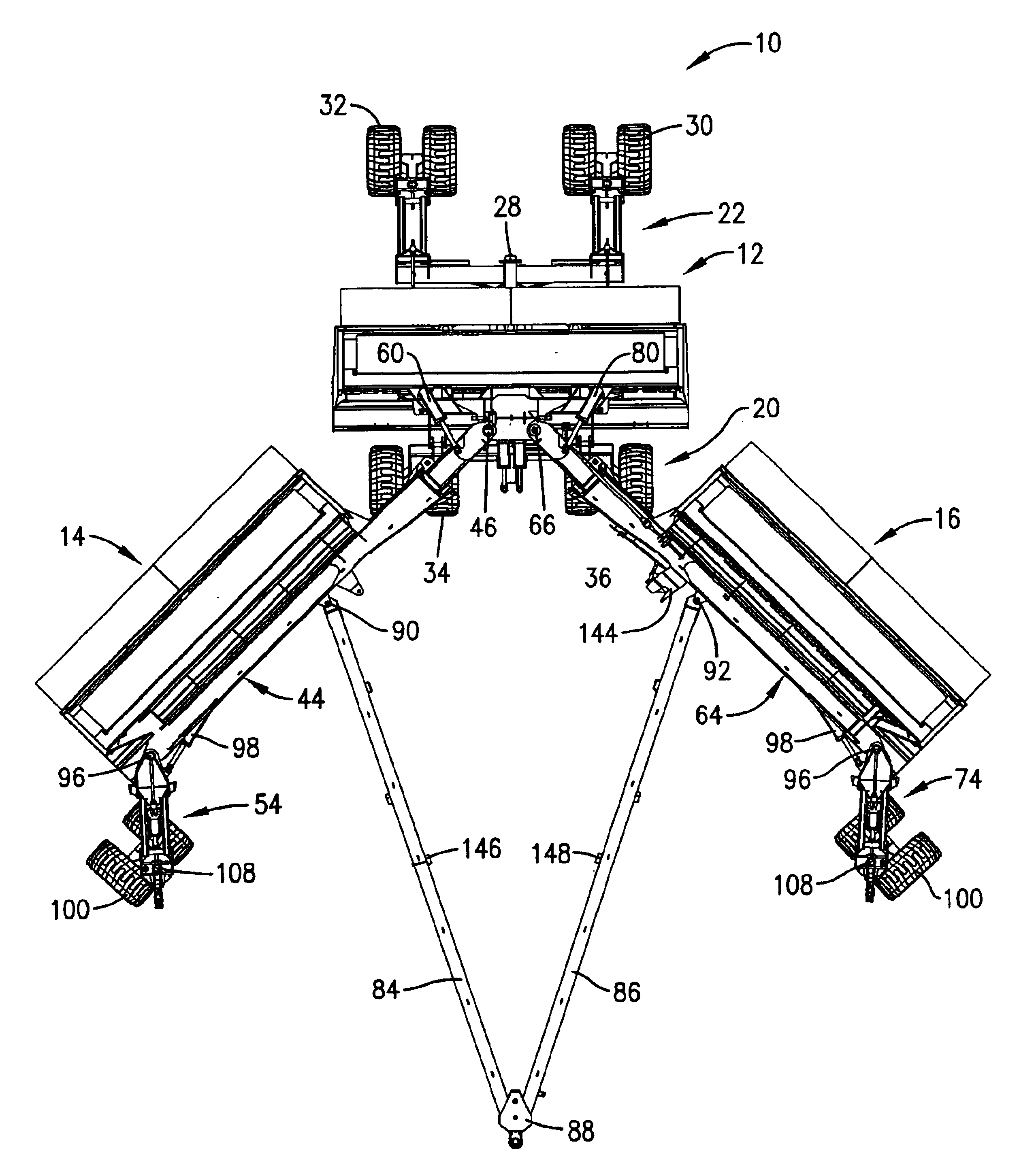
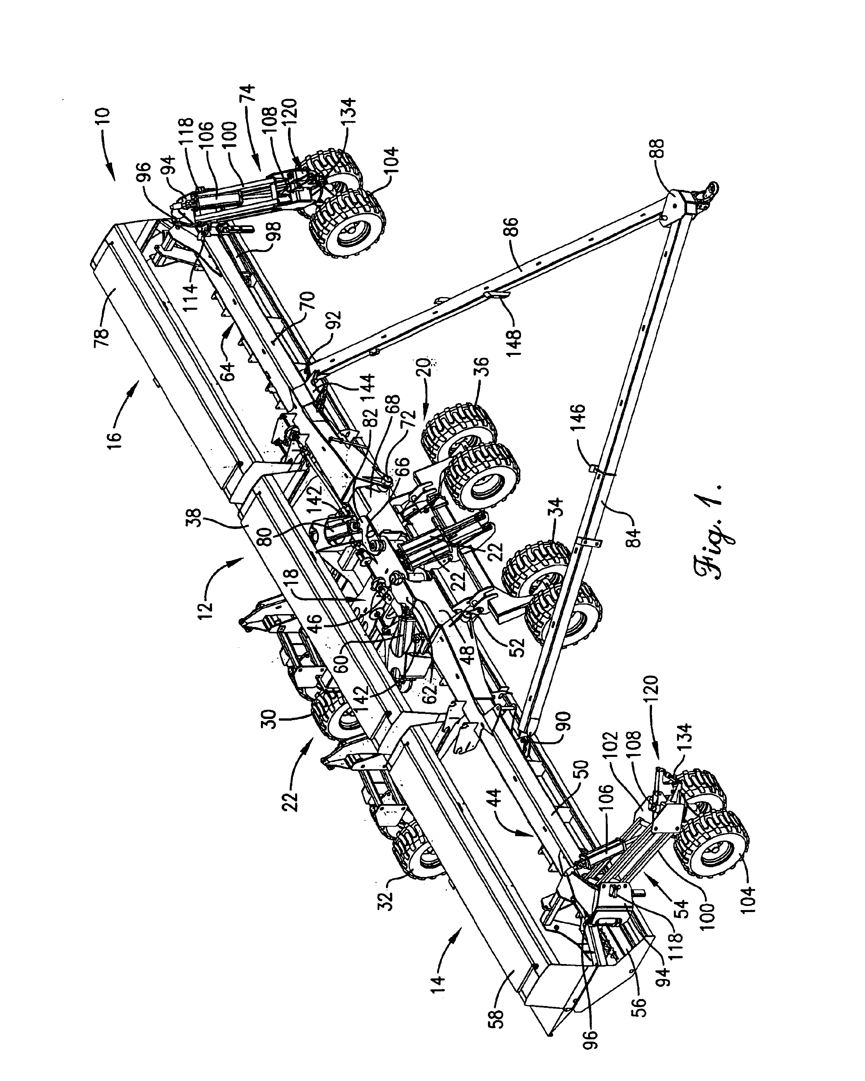
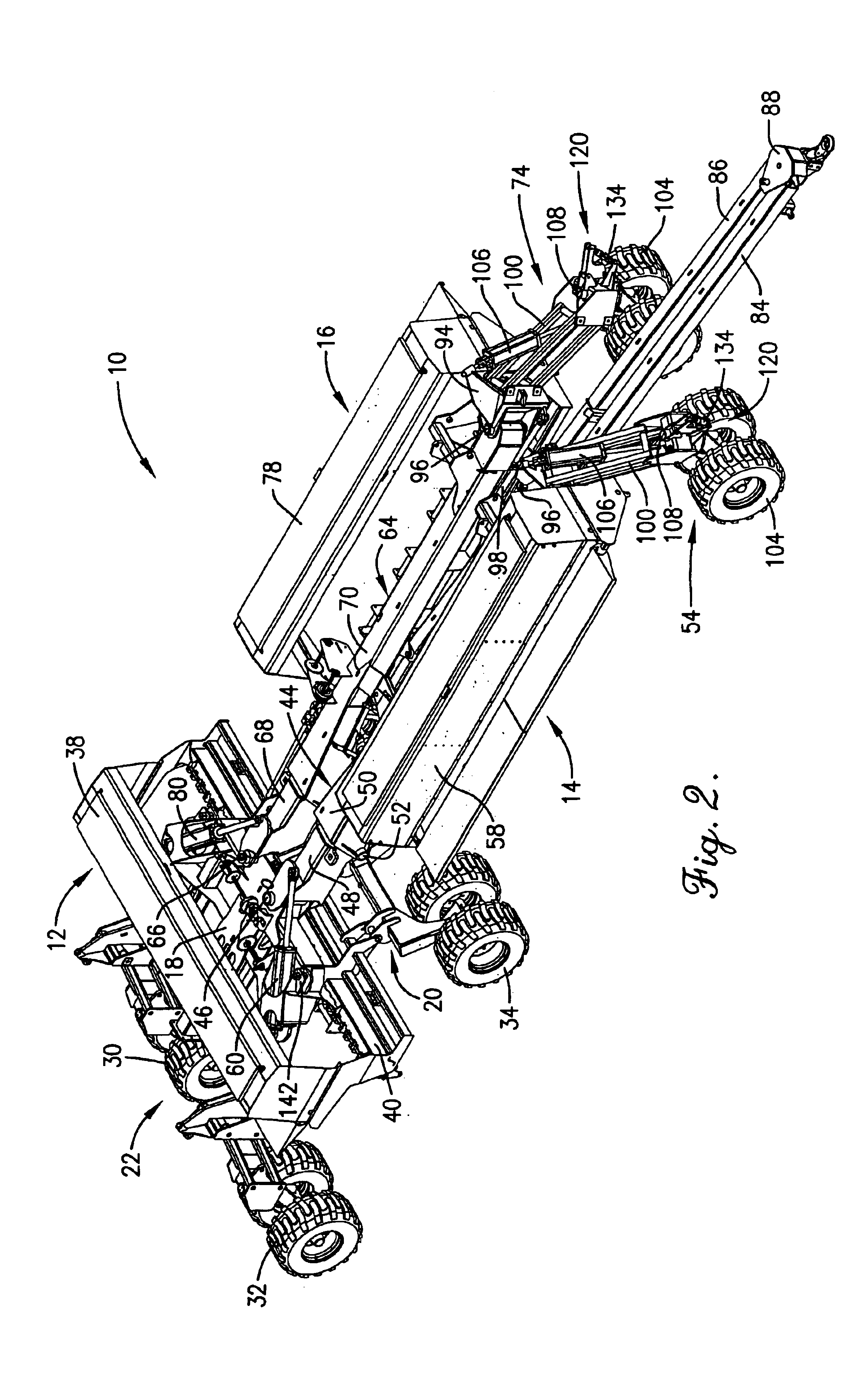
The implement 10 disclosed herein for purposes of illustration comprises a three section seeding machine, although almost all the openers of such machine have been removed to simplify the drawings and promote an understanding of the principles of the invention. As will be apparent, the principles of the present invention are applicable to many different types of folding implements and are not limited to machines having three sections. Some of the principles of the invention are applicable to rear folding machines as well as front folding machines.

In the illustrated embodiment the three section implement 10 includes a center ...


PUM


Abstract

A multiple section, front-folding implement has gauge wheel assemblies located on the front side of laterally extending beams of the sections during field operations. As the wing sections are folded forwardly to prepare the machine for transport, the gauge wheel assemblies are simultaneously swung around to the ends of the beams into outboard positions so that they extend generally forwardly from the beams when the beams are fully folded. Thus, instead of taking up space between the folded beams, the gauge wheel assemblies are moved into clearance positions that enable the wing sections to be folded more closely together, reducing the overall roading width of the machine when folded.

Description

TECHNICAL FIELDThis invention relates to farm equipment such as planters and drills and, more particularly, to a way of folding such machines into a relatively narrow roading width.BACKGROUND AND SUMMARYIt is known in the art to fold multiple section planters and drills forwardly from wide spread field positions to narrowed transport positions. However, in many multiple sections machines gauge wheels on the wing sections project forwardly from the front side of the sections and thus tend to interfere with one another when the sections are folded together. To avoid these interference problems, pivot points for the wing sections are typically spaced far enough apart to keep the gauge wheels from interfering with one another when the machine is in its folded condition. However, this necessarily increases the overall width of the folded machine.The present invention solves this problem by making the gauge wheel assemblies shiftable from their positions on the front side of the wing sect...

Claims


Application Information

Patent Timeline
01 Mar 2005
Publication
US6860335B2
IPC
A01B73/06; A01B73/00
CPC
A01B73/065
Inventors
ARNETT, GREGORY W.