
Multiple chamber dual stage inflator

a gas generator and multi-chamber technology, applied in the direction of pedestrian/occupant safety arrangement, vehicle components, chemistry apparatus and processes, etc., can solve the problems of airbags affecting the occupants with a greater force than necessary, affecting the occupants with a greater force, and causing significant cost and complexity, so as to reduce manufacturing costs, reduce tooling, and eliminate the need for part differentiation during the assembly process

Inactive Publication Date: 2005-03-01
AUTOMOTIVE SYST LAB
View PDF9 Cites 12 Cited by
  • Summary
  • Abstract
  • Description
  • Claims
  • Application Information

AI Technical Summary

Benefits of technology

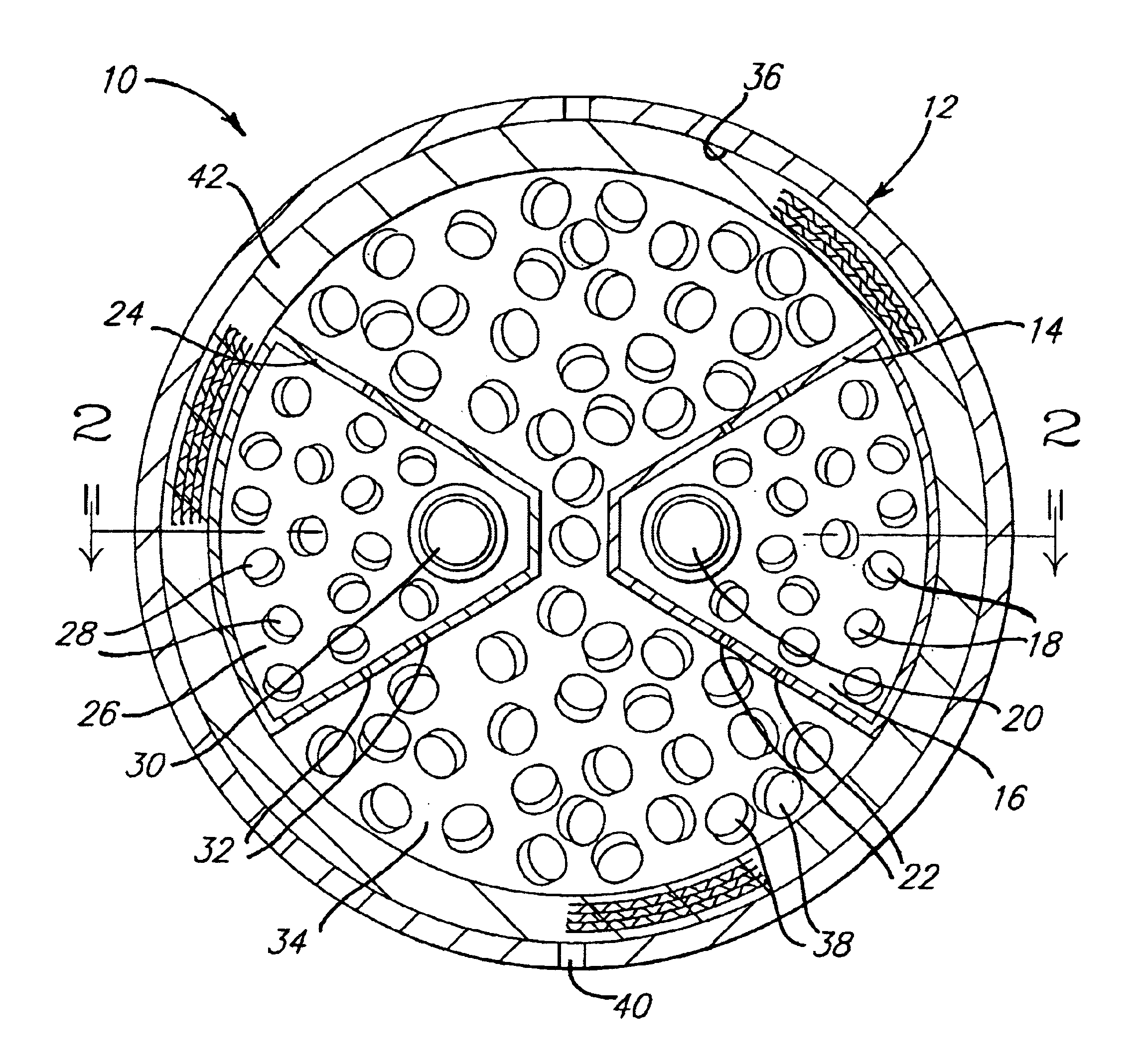
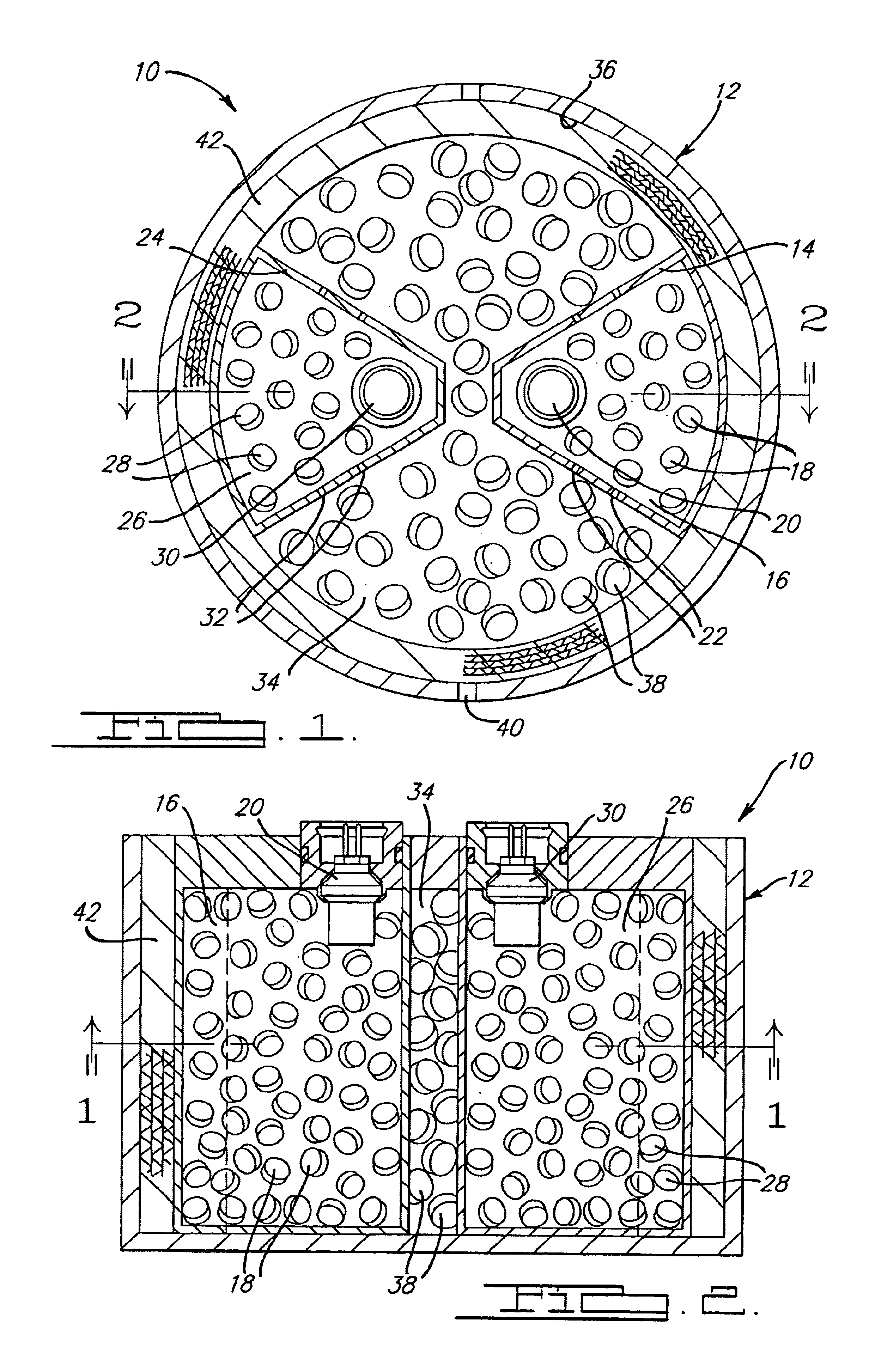
In accordance with the present invention, the first and second chambers are of equivalent dimension and volume. The first and second gas generant compositions are preferably of equal composition and in equal amounts, or, may be of different compositions and / or of different amounts. When the first and second chambers contain the same gas generant composition and in identical amounts, the need for part differentiation during the assembly process is eliminated. This reduces assembly error when connecting the system circuitry to the first and second igniters for the circuits communicating with either the first or second igniters fire equivalent systems. The first and second chambers are preferably disposed symmetrically within the primary chamber. Use of equal-sized first and second chambers requires less tooling, thereby reducing manufacturing costs and simultaneously reducing manufacturing and assembly complexity.

Problems solved by technology

However, air bag inflation systems utilizing a single gas generator suffer from the disadvantage that the onset pressurization / inflation rate is generally set to provide aggressive initial inflation in order to achieve a particular inflation time related to occupant position.
An aggressive onset rate of pressurization becomes problematic in situations where the occupant is out of position.
More specifically, rapid onset pressurization of the air bag may cause the air bag to impact against the occupant with a greater force than necessary.
While this arrangement dramatically improves the inflation system's ability to protect an occupant, it does so at significant expense and complexity.
The multiple gas generators and squibs add considerable cost to the system, while the firing control circuitry requires sophisticated processors capable of accurately timing the various ignition profiles.
However, this design appears to accommodate passenger-side inflators only.
One concern is that this approach necessarily complicates the manufacturing process in that the inflator contains additional parts.
Also, the system algorithm employed to process the occupant size and / or position data is necessarily more complex in that more choices or outcomes are required to accommodate the various permutations or combinations of firing the various chambers.

Method used


Image

  • Multiple chamber dual stage inflator
  • Multiple chamber dual stage inflator

Examples


Embodiment Construction

A multiple chamber inflator 10 contains a perforate housing 12. The housing is initially sealed to facilitate a pressure buildup upon inflator 10 operation. A first wall 14 is fixed or disposed within the housing 12 and forms a first chamber 16. A first gas generant composition or propellant 18 is housed within the chamber 16 and provides a first inflating gas upon selective combustion thereof. A first igniter 20 is fixed or disposed within the chamber 16 and in a known manner ignites the propellant 18 upon receipt from a crash sensor algorithm, for example. A first at least one gas exit orifice 22 and preferably a plurality of gas exit orifices 22 provides fluid communication between the first inflating gas and any attendant flame front with the interior of the housing 12. The orifice(s) 22 is sealed prior to activation of the first chamber 16 thereby insulating the chamber from exterior combustion.

In accordance with the present invention, a second wall 24 is fixed or disposed with...


PUM


Abstract

A dual stage inflator 10 utilizes a housing 12 having two supplemental propellant combustion chambers 16 and 26, both symmetrically oriented within a primary propellant combustion chamber 34. Chambers 16 and 26 are formed to be substantially equivalent in dimensions and volume thereby simplifying the assembly and manufacturing process.

Description

FIELD OF THE INVENTIONThe present invention relates to gas generators, used to inflate air bags in a vehicle occupant protection system for example, and more particularly, to an improved dual chamber gas generator containing an improved structure for isolating the propellant chambers of a dual chamber inflator so as to ensure proper deployment of the airbag while yet simplifying the manufacture thereofBACKGROUND OF THE INVENTIONInflation systems for deploying an air bag in a motor vehicle generally employ a single gas generator in fluid communication with an uninflated air bag. A firing circuit typically triggers the gas generator when the sensed vehicle acceleration exceeds a predetermined threshold value, as through the use of an acceleration-responsive inertial switch.However, air bag inflation systems utilizing a single gas generator suffer from the disadvantage that the onset pressurization / inflation rate is generally set to provide aggressive initial inflation in order to achi...

Claims


Application Information

Patent Timeline
Patent Type & Authority Patents(United States)
IPC IPC(8): B60R21/26B01J7/00B60RB60R21/263B60R21/264
CPCB60R21/2644B60R2021/2648B60R2021/2633
Inventor PATTERSON, DONALD B.
Owner AUTOMOTIVE SYST LAB
Learn More