Slidable truck bed-supported cargo carrier assembly

a truck bed and cargo carrier technology, applied in the field of sliding truck beds, can solve the problem of not disclosing the new slidable truck bed and cargo carrier assembly, and achieve the effects of convenient loading and unloading of items, convenient and convenient use, and convenient reach for users

Inactive Publication Date: 2005-03-01
SCHIMUNEK KERRY W
View PDF23 Cites 45 Cited by
  • Summary
  • Abstract
  • Description
  • Claims
  • Application Information

AI Technical Summary

Benefits of technology

Still another object of the present invention is to provide a new slidable truck bed-supported cargo carrier assembly for facilitating the loading and unloading of items and objects from truck boxes.
Still yet another object of the present invention is to provide a new slidable truc

Problems solved by technology

While these devices fulfill their respective, particular objectives and requirements, the afo

Method used


Image

  • Slidable truck bed-supported cargo carrier assembly
  • Slidable truck bed-supported cargo carrier assembly
  • Slidable truck bed-supported cargo carrier assembly

Examples


Embodiment Construction

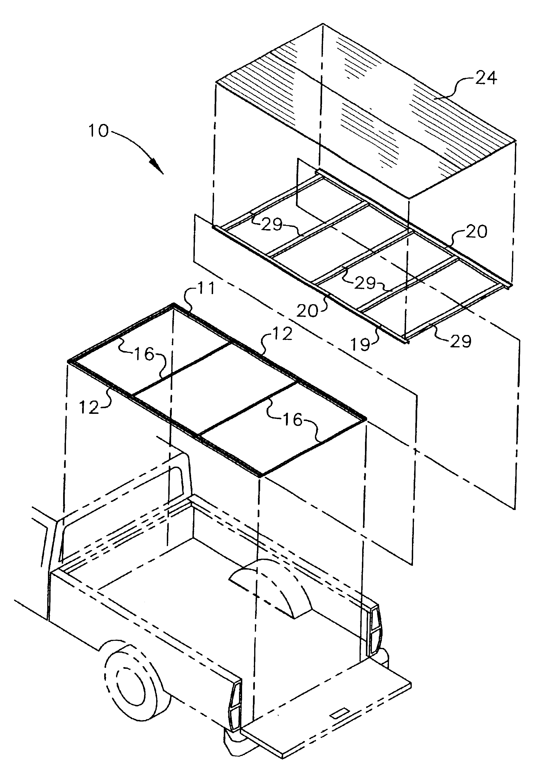
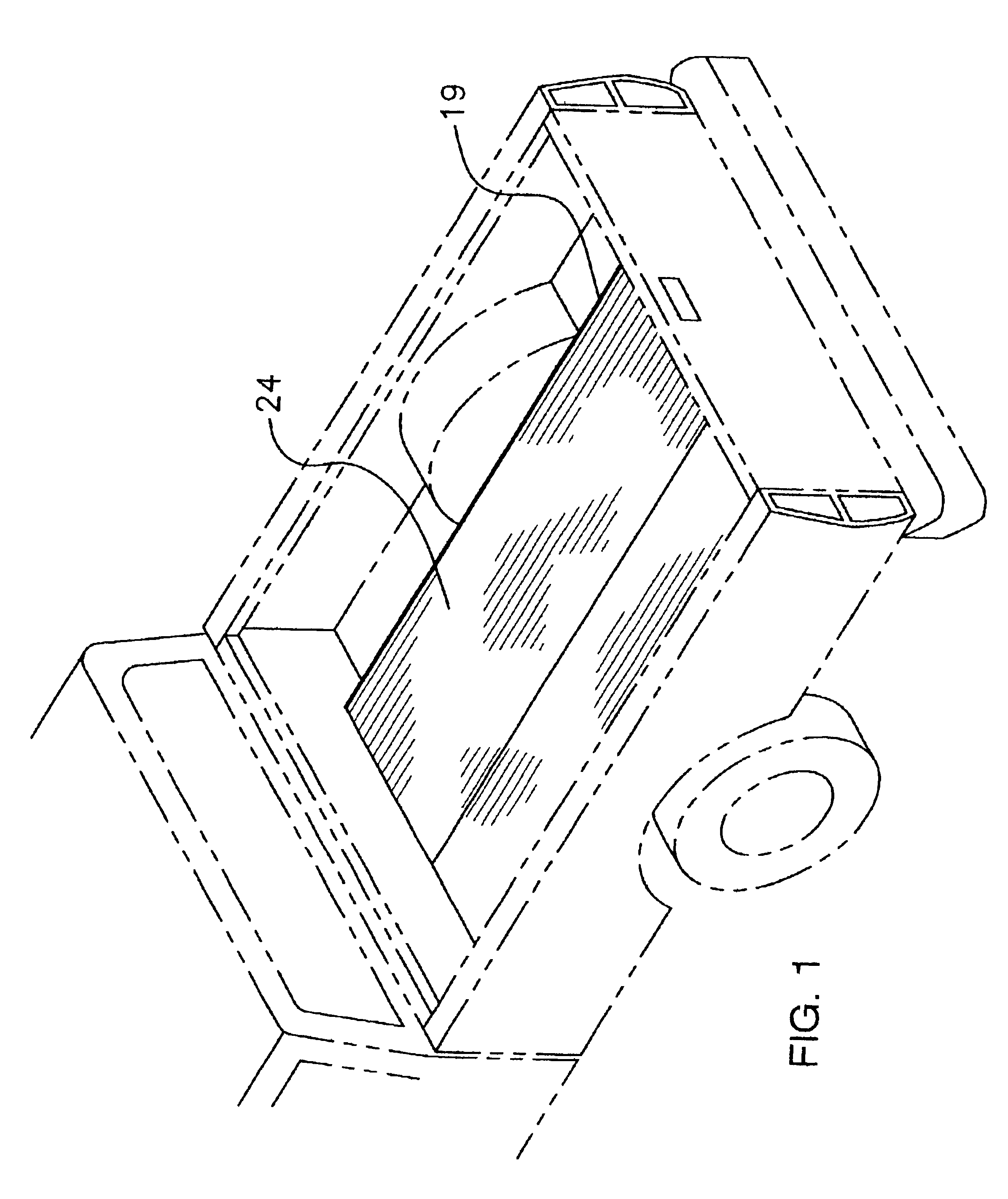
With reference now to the drawings, and in particular to FIGS. 1 through 6 thereof, a new slidable truck bed-supported cargo carrier assembly embodying the principles and concepts of the present invention and generally designated by the reference numeral 10 will be described.

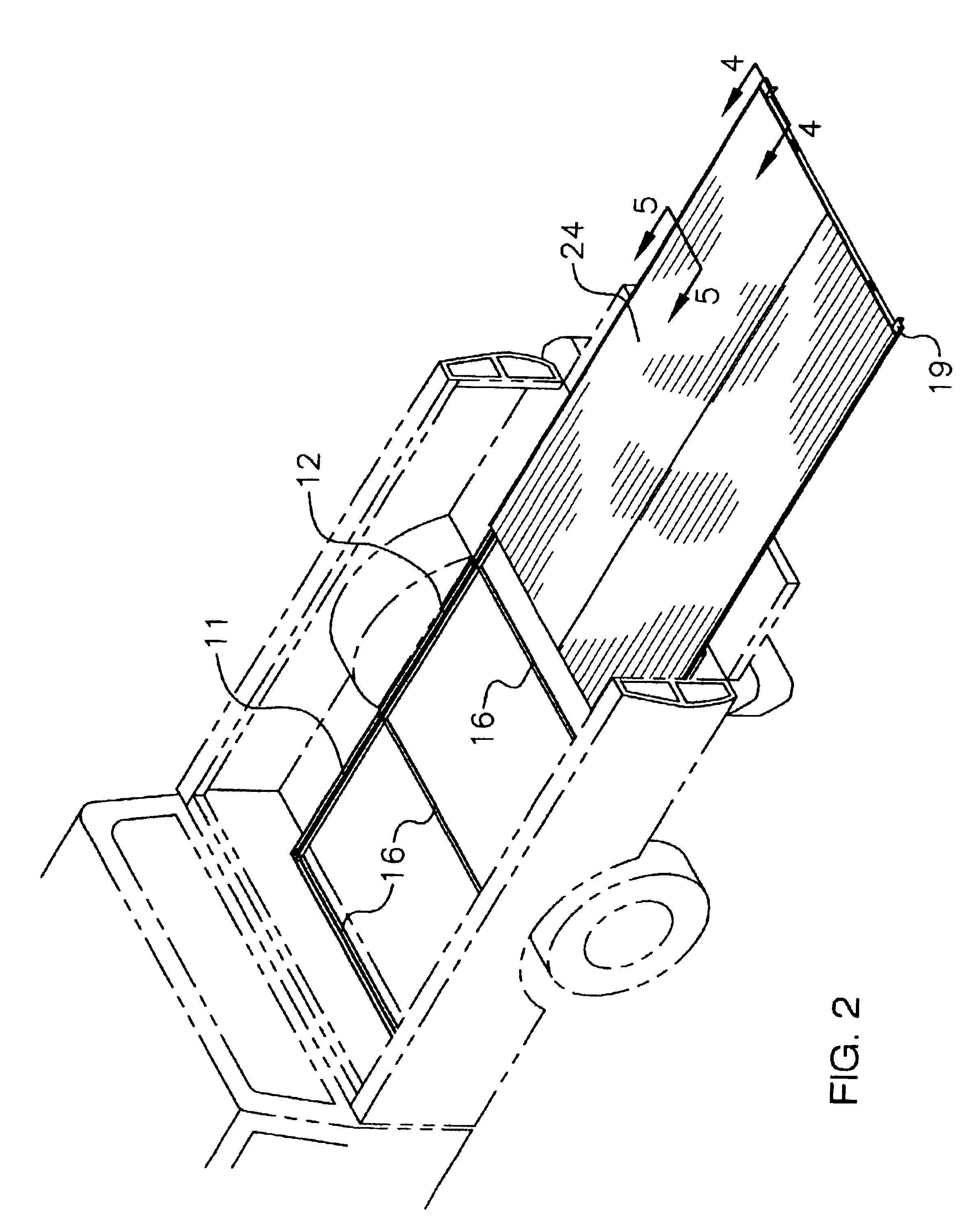
As best illustrated in FIGS. 1 through 6, the slidable truck bed-supported cargo carrier assembly 10 generally comprises a base support assembly including a base support frame 11 being adapted to rest upon a floor of a truck box, and also including roller assemblies being conventionally attached to the base support frame 11. The base support frame 11 includes elongate side members 12 being spaced apart and being adapted to be fastened to the floor of the truck box, and also includes cross members 16 being attached to the elongate side members 12 for stabilizing the elongate side members 12. Each of the elongate side members 12 has a U-shaped lateral cross-section which includes an elongate main portion 13 and lo...


PUM


Abstract

A slidable truck bed-supported cargo carrier assembly for facilitating the loading and unloading of items and objects from truck boxes. The slidable truck bed-supported cargo carrier assembly includes a base support assembly including a base support frame being adapted to rest upon a floor of a truck box, and also including roller assemblies being attached to base support frame; and also includes a deck support frame being slidably disposed upon the base support assembly; and further includes a deck being mounted upon the deck support frame; and also includes a locking assembly for securing the deck support frame to the base support frame.

Description

BACKGROUND OF THE INVENTION1. Field of the InventionThe present invention relates to slidable truck beds and more particularly pertains to a new slidable truck bed-supported cargo carrier assembly for facilitating the loading and unloading of items and objects from truck boxes.2. Description of the Prior ArtThe use of slidable truck beds is known in the prior art. More specifically, slidable truck beds heretofore devised and utilized are known to consist basically of familiar, expected and obvious structural configurations, notwithstanding the myriad of designs encompassed by the crowded prior art which have been developed for the fulfillment of countless objectives and requirements.Known prior art includes U.S. Pat. No. 5,513,941; U.S. Pat. No. 5,938,262; U.S. Pat. No. 5,052,878; U.S. Pat. No. 6,065,792; U.S. Pat. No. 4,950,123; and U.S. Pat. No. Des. 257,966.While these devices fulfill their respective, particular objectives and requirements, the aforementioned patents do not disc...

Claims


Application Information

Patent Timeline
IPC IPC(8): B60P1/00B60R11/00B60R13/01
CPCB60P1/003B60R13/01B60R11/00B60R2011/0084
Inventor SCHIMUNEK, KERRY W.
Owner SCHIMUNEK KERRY W
Why Eureka
Try Eureka