Spherical bearing

a bearing and spherical technology, applied in the direction of bearings, shafts and bearings, rotary bearings, etc., can solve the problems of early failure of conventional cylindrical sleeve bearings

Inactive Publication Date: 2005-03-01
POLYGON
View PDF12 Cites 22 Cited by
  • Summary
  • Abstract
  • Description
  • Claims
  • Application Information

AI Technical Summary

Benefits of technology

An advantage of the present invention is that the elastic nature of the retaining surface allows the spherical bearing portion to be snapped into place.
Another advantage is that at least one of the surfaces of the bearing interface is self lubricating.
Yet another advantage is that the bearing surface has a self-healing characteristic.
A further advantage of the present invention is that the lubricating film if removed replenishes itself from the surrounding material.
A still further advantage is that the present invention provides a dampening characteristic to shock or impact loads due to the elastic characteristics of the composite structure.
Another still further advantage is that the present invention is several times more elastic under radial load than metallic bearings, thereby providing a cushioning feature under shock load conditions.

Problems solved by technology

Machining and distortion misalignment difficulties normally generate considerable end loading and cause the early failure of conventional cylindrical sleeve bearings.

Method used


Image

  • Spherical bearing
  • Spherical bearing
  • Spherical bearing

Examples


Embodiment Construction

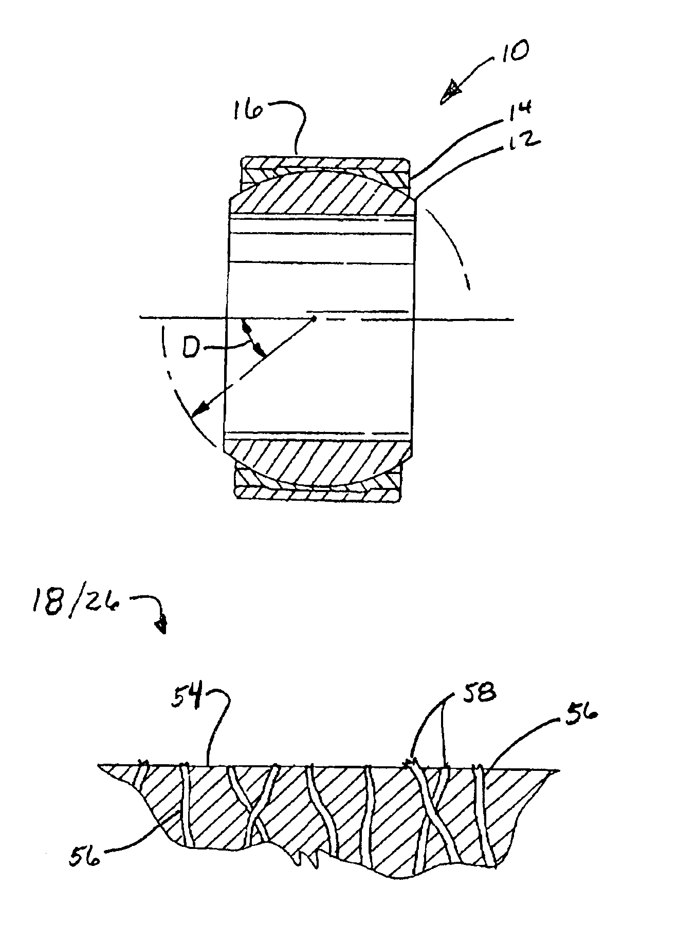
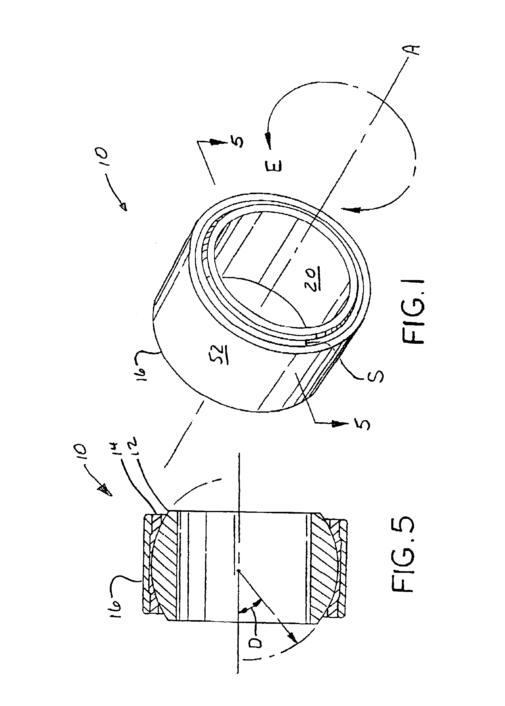
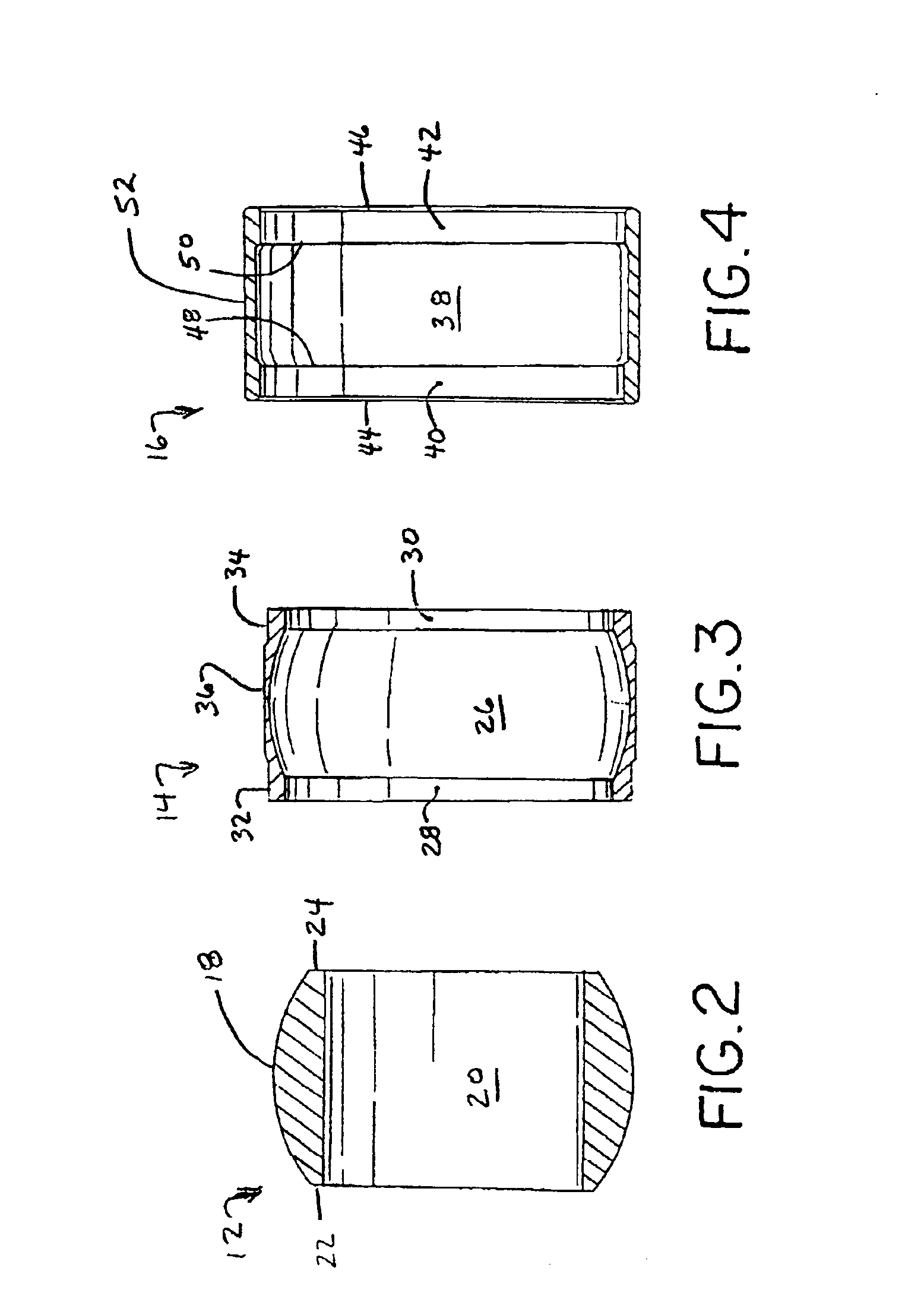
Referring now to the drawings, and more particularly to FIGS. 1-5, there is shown a spherical bearing assembly 10 which generally includes a first bearing portion 12, a second bearing portion 14 and a third bearing portion 16.

First bearing portion 12, also known as spherical portion 12, includes a substantially convex spherical outer surface 18, a substantially cylindrical inner surface 20, a first shoulder 22 and a second shoulder 24. Spherical outer surface 18 is shaped to interface with intermediate portion 14. Outer surface 18 may be finished to a relatively smooth surface finish. Cylindrical inner surface 20 is sized to accommodate a shaft or fastening device to connect spherical portion 12 to another movable object (not shown). Alternatively, cylindrical inner surface 20 may be replaced with an integral protruding part to which a linking item may be connected (not shown). Shoulders 22 and 24 are provided to allow a fastening device to be secured thereagainst.

Second portion 14,...


PUM


Abstract

A spherical bearing including a generally annular first portion having at least a partial substantially spherical outer surface and a generally annular second portion having at least a partial substantially concave surface, the outer surface at least partially engaging the concave surface, at least one of the outer surface and the concave surface having a plurality of frayed polytetraflouroethylene fibers exposed therefrom.

Description

BACKGROUND OF THE INVENTION1. Field of the InventionThe present invention relates to a spherical bearing, and, more particularly, to a composite spherical bearing.2. Description of the Related ArtSpherical and semi-spherical bearings are known. A typical spherical bearing may include an inner partially spherical bearing with a surface that interacts with a substantially spherical concave outer retaining portion. The retaining portion may be connected to a linkage or similar mechanical device. A shaft is often attached to the inner spherical portion or is integral with the inner spherical portion such as a tie rod end on a vehicle.Spherical bearings have spherical contact surfaces which allow the inner ring to rotate freely with multiple degrees of freedom while positioned within the bearing outer retaining portion. The multiple degrees of freedom allows a spherical bearing the ability to self-align such that it automatically adjusts to any misalignment, which may occur due to applic...

Claims


Application Information

Patent Timeline
Patent Type & Authority Patents(United States)
IPC IPC(8): F16C33/04F16C23/00F16C33/20F16C23/04
CPCF16C33/201F16C23/045
Inventor FISH, ELSON B.
Owner POLYGON
Why Eureka
Try Eureka