Vacuum driven sander

Inactive Publication Date: 2005-03-01
LOVELESS MICHAEL L
View PDF32 Cites 63 Cited by
  • Summary
  • Abstract
  • Description
  • Claims
  • Application Information

AI Technical Summary

Benefits of technology

It is a principal object of the present invention to provide an improved vacuum air driven turbine operated sander that includes a coupl

Problems solved by technology

None of which earlier sanding devices prior to that of the '985 patent of the inventor, however, included a vacuum driven oscillating sanding disk that provided for the efficient and reliable removal of sanded particles from the work surface through an attached vacuum hose.
However, while the patent to Rodowsky, Jr. et al., U.S. Pat. No. 4,399,638 provides a turbine blade that is turned by a vacuum flow to operate an oscillating plate whereto a section of sanding material is attached, calls for pulling that sanded dust through the turbine bearing, thereby greatly limiting bearing life.
The '985 patent also provided an improved pole coupling assembly tha

Method used


Image

  • Vacuum driven sander
  • Vacuum driven sander
  • Vacuum driven sander

Examples


Embodiment Construction

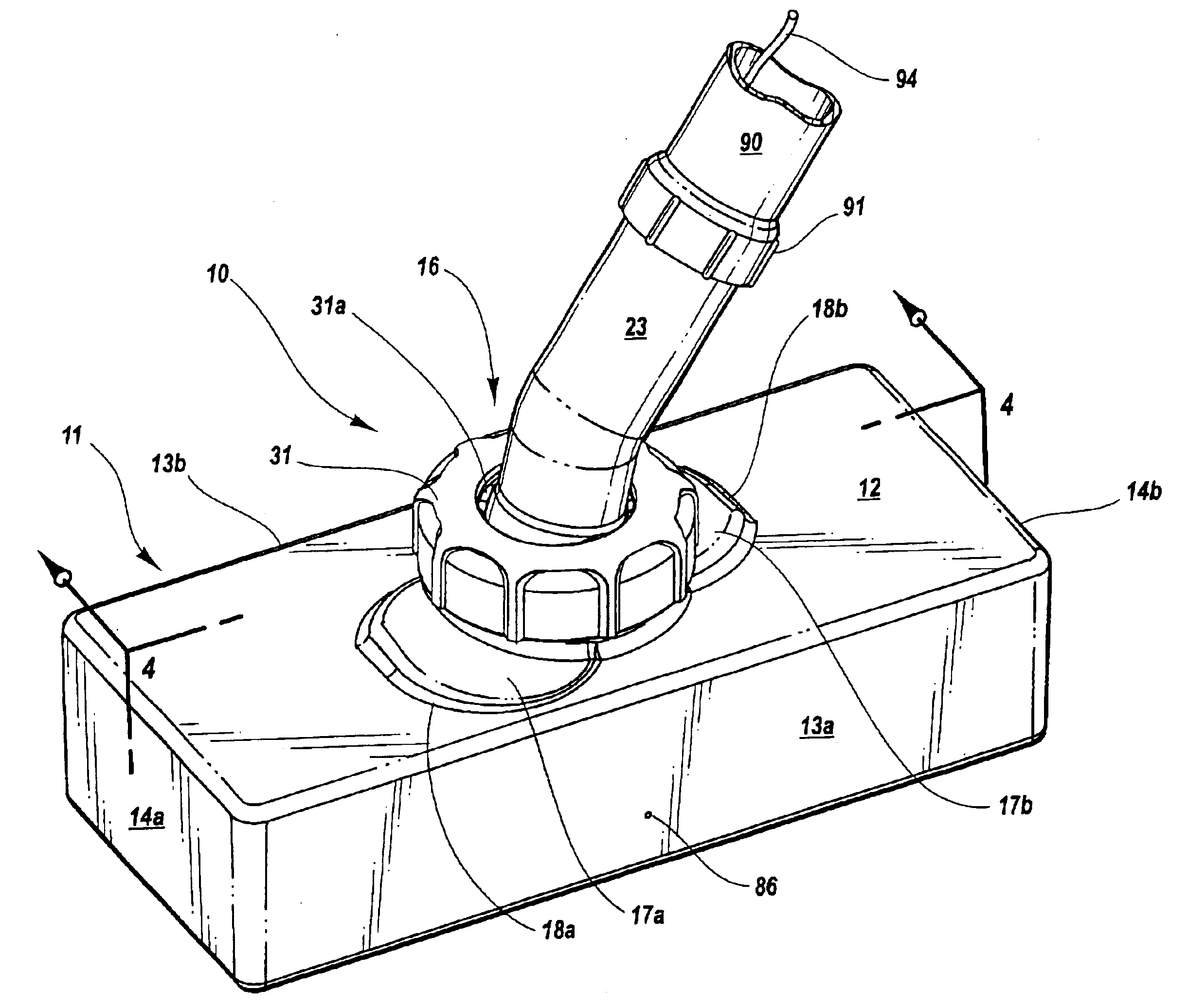
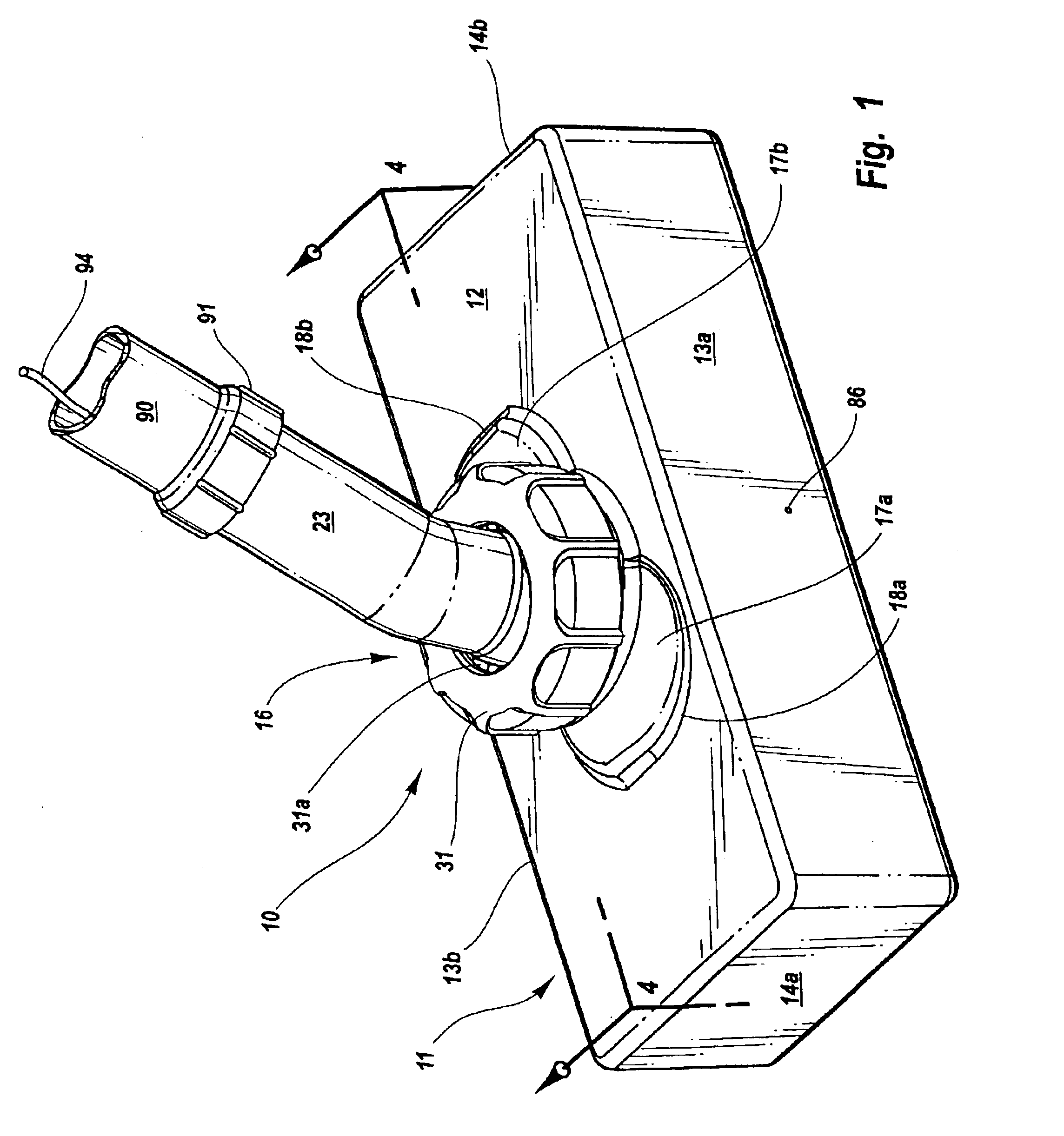
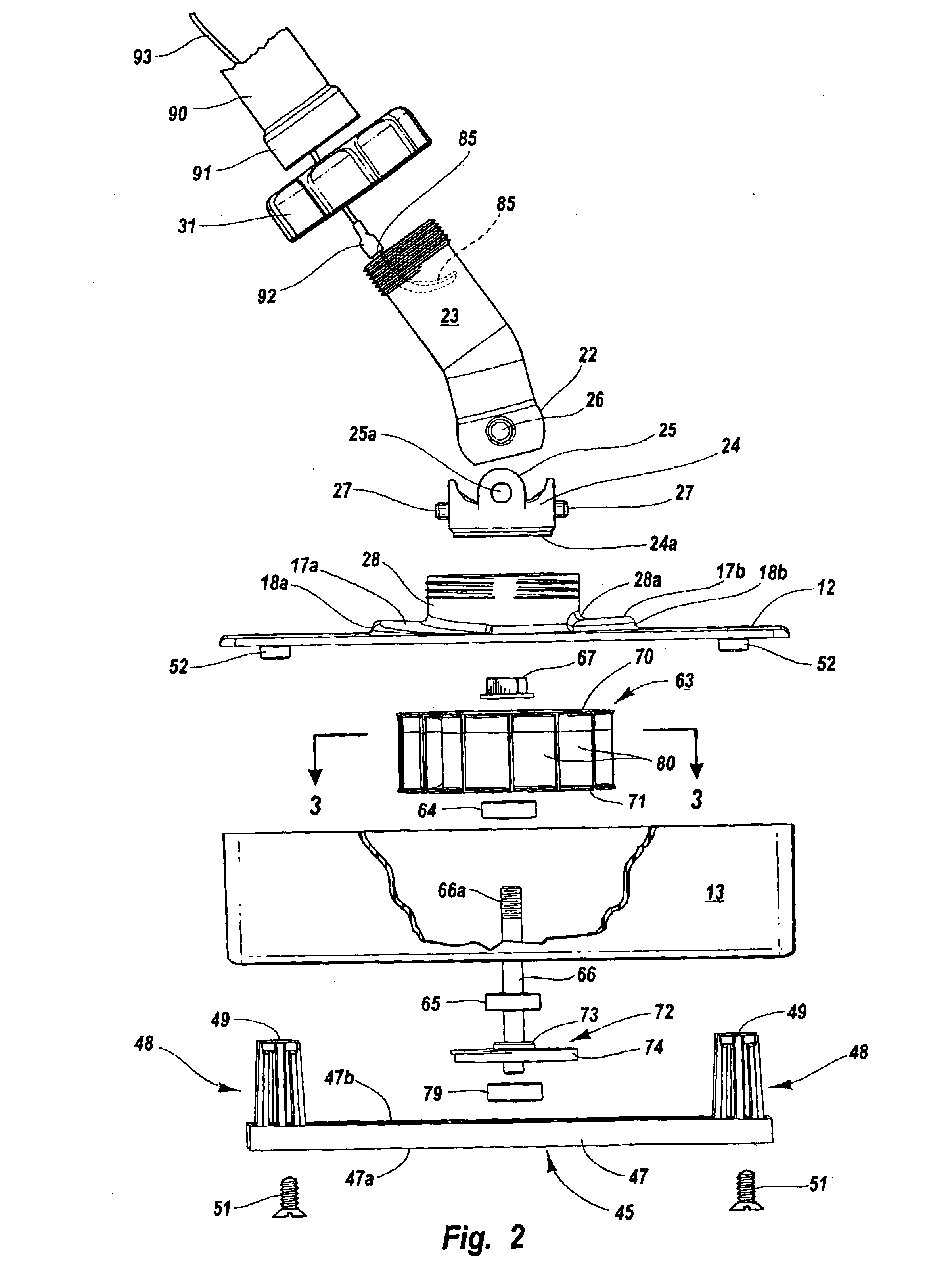
The invention is herein described with reference to a preferred embodiment shown in the accompanying drawings, with FIG. 1 showing a front elevation perspective view of the low profile vacuum driven sander 10 of the invention, hereinafter referred to as sander. As shown in the Figs., the sander 10 includes a housing 11, having front, rear and side walls 13a, 13b, 14a, and 14b, respectively, extending at right angles downwardly from a housing top edge, forming an inverted narrow rectangular box configuration having, as shown in FIG. 4 an open bottom 15. A coupling collar assembly 16 that is open therethrough is shown in FIGS. 1,3 and 4, fitted into the center of the top 12 that includes, as shown in FIGS. 2 and 5, a pair of turbine ducts 17a and 17b that are shown as flat raised sections that extend oppositely from steps 18a and 18b to an opening in the center of the flat top 12, and open into the coupling collar assembly, as shown in FIG. 4, to serve as ducts to pass and direct a tu...


PUM


Abstract

The invention is in a vacuum driven sander that is appropriate for drywall sanding, that utilizes a vacuum flow pulled therethrough to drive a turbine that includes an adjustable lock mounting through a bearing assembly to an eccentric to turn the eccentric that is connected to oscillate a sanding pad that mounts a section of sanding material, and that vacuum air flow also provides for removing sanded particles off from the sanded surface that are transported through the sander and a connected pipe or hose into a catchment container. The sander housing includes a pole mounting cylinder that projects outwardly from a housing top surface and is ported with equal spaced radial cavities formed around the port, and with a selected pair of cavities to receive each of a pair of stub axles of a pivot collar, providing a first pivot coupling that, along with a second pivot mounting of the collar to the end of a hollow bent tube, provides a universal coupling of the hollow bent tube to the sander body that allows for the pivoting of the sander whereby the sanding surface remains in engagement with the wall as it is moved up and down and across the wall. The hollow bent tube also includes a static discharge electrical connector that receives a female connector fixed to an end of a conductive wire for positioning in a sander pole that is mounted to the bent tube end, with the wire extending the length of the pole wherethrough the vacuum exhaust flow passes and conducts a static electric charge into the vacuum flow.

Description

BACKGROUND OF THE INVENTION1. Field of the InventionThis invention pertains to sanding devices, and in particular to a vacuum driven light weight sander that can be hand held or mounted onto a pole for use in sanding dry wall and is attached to a vacuum hose that provides motive power to drive the sander and for removing sanding dust off of a wall surface that is pulled into a collection canister.2. Prior ArtThe present invention is in improvements to a vacuum driven sander as embodied in U.S. Pat. No. 6,347,985 issued to the present inventor. The vacuum driven sander of the '985 patent constitutes a marked improvement over earlier sanders. With some examples of such earlier sanding devices are shown, in U.S. utility patents to Brenner U.S. Pat. No. 3,722,147; to Mehrer U.S. Pat. No. 4,062,152; to Marton U.S. Pat. No. 4,184,291; to Rodowsky, Jr. et al. U.S. Pat. No. 4,399,683; to Romine U.S. Pat. No. 4,697,389; to Paterson U.S. Pat. No. 5,007,206; to Sanchez, et al. U.S. Pat. No. 5,...

Claims


Application Information

Patent Timeline
IPC IPC(8): B24B23/00B24B23/04
CPCB24B23/043
Inventor LOVELESS, MICHAEL L.
Owner LOVELESS MICHAEL L
Why Eureka
Try Eureka