Stable coil designs

a coil design and coil technology, applied in the field of stable coil designs and vasoocclusive devices, can solve the problems that none of these devices are stable coil designs with complex three-dimensional winding patterns, and achieve the effect of enhancing the utility of the devi

Inactive Publication Date: 2005-03-01
STRYKER CORP +1
View PDF28 Cites 227 Cited by
  • Summary
  • Abstract
  • Description
  • Claims
  • Application Information

AI Technical Summary

Benefits of technology

This invention is a vaso-occlusive device comprising one or more vaso-occlusive members which are wound to form complex winding patterns when relaxed. The vaso-occlusive member itself may be a helically wound coil or braid typically comprising a biocompatible metal. Fibrous materials may be woven into the member or tied or wrapped onto it. The stable coils of the invention are formed by first winding a wire into a first helix; the first helix is then wound into a secondary form which is wound back onto itself, for example on a mandrel, to form two or more layers of the primary coil. The reverse winding may be on the same axis as the first winding axis or may be on a different axis. The overall form may be selected to be a variety of shapes deployed, including generally spheroid, elliptical, clover or box shapes. Generally, the shape of the relaxed configuration is formed by the outermost loops of the primary coil having the largest diameter. Loops having smaller diameters pass through the relaxed configuration. Desirably, the vaso-occlusive device is of a size and shape suitable for fitting snugly within a vascular cavity (e.g., an aneurysm, or perhaps, near a fistula). The stiffness of the various parts of the coil may be selected to enhance the utility of the device for specific applications. Fibrous materials may be woven into the member or tied or wrapped onto it.

Problems solved by technology

None of these devices are stable coil designs having complex three-dimensional winding patterns.

Method used


Image

  • Stable coil designs
  • Stable coil designs
  • Stable coil designs

Examples


Embodiment Construction

Throughout this application, various publications, patents, and published patent applications are referred to by an identifying citation. The disclosure of the publications, patents, and published patent specifications referenced in this application are hereby incorporated by reference into the present disclosure to more fully describe the state of the art to which this invention pertains.

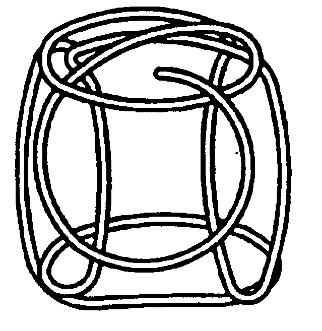
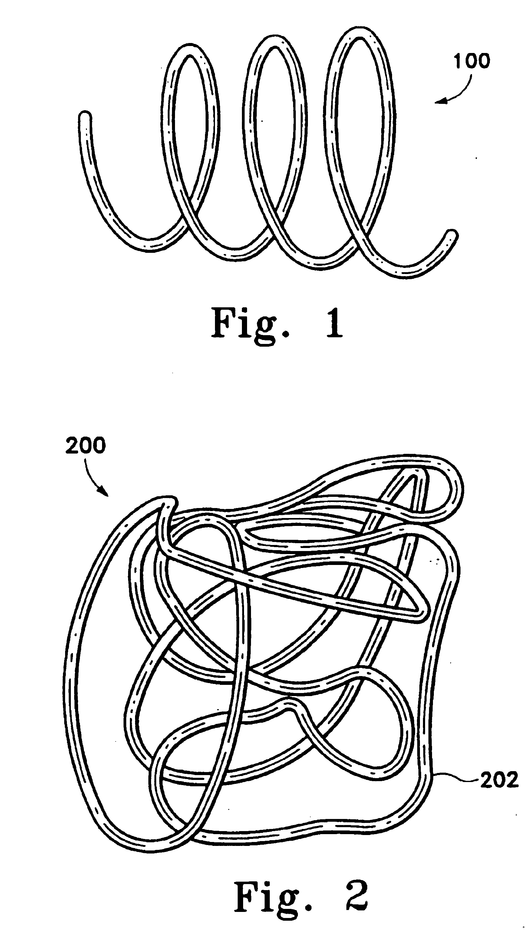
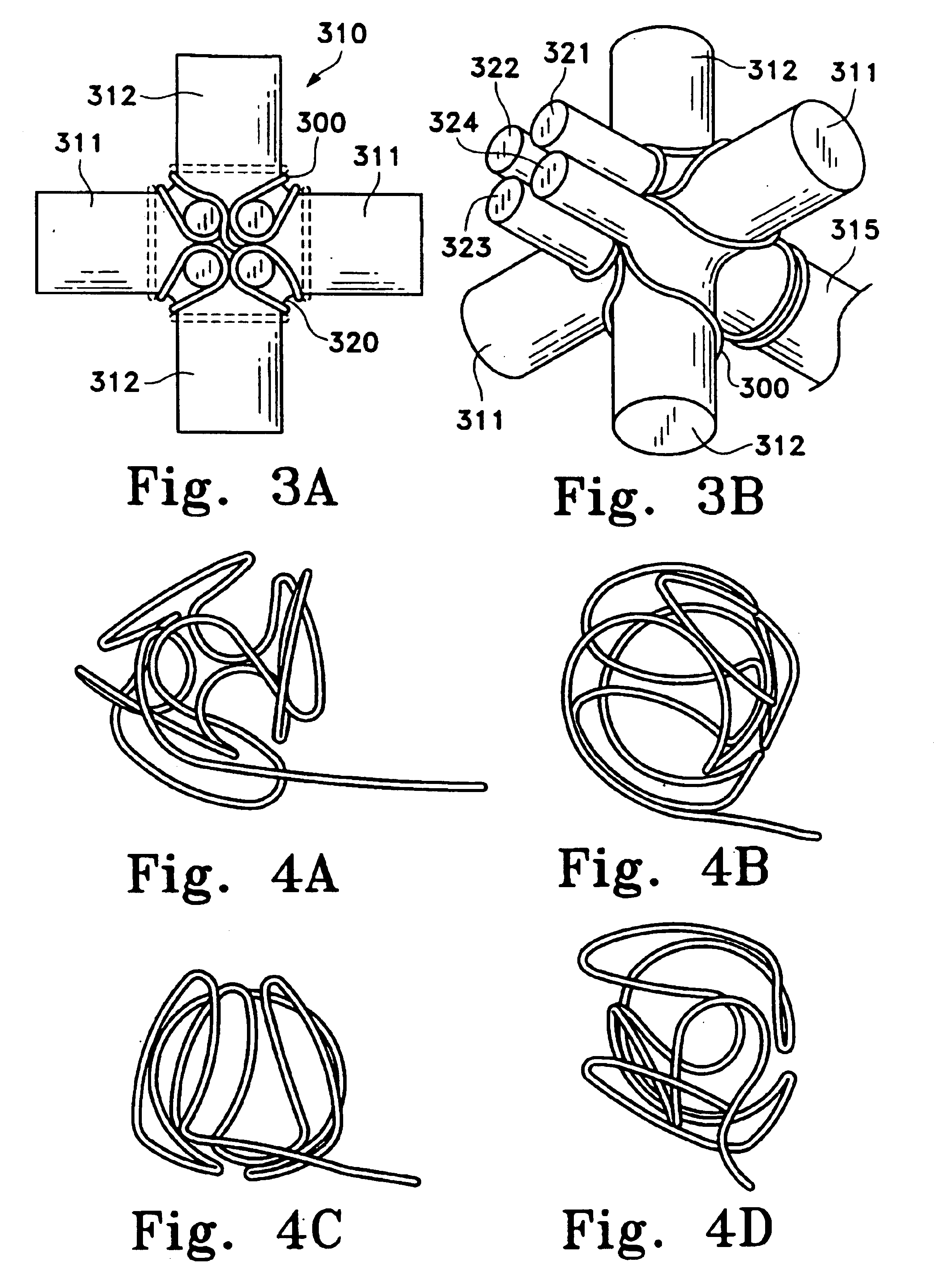
The complex coil designs of the present invention are particularly useful in treating aneurysms. The shapes described herein provide an improved blood flow baffle design at the neck and dome of the aneurysm, thereby providing extra protection for aneurysms which because of their fragility cannot be densely packed with other coil types. The basket-shaped coil, for instance, is easily packed into the aneurysm. The stability of the coils of the present invention reduces the incidence of coil compaction, a phenomena that may occur over time when coils move back to the shape of their first configuration...


PUM


Abstract

This is an implantable vaso-occlusive device. The device has a complex, three-dimensional structure in a relaxed configuration that may be used in the approximate shape of an anatomical cavity. It may be deployed in the approximate shape of a sphere, an ovoid, a clover, a box-like structure or other distorted spherical shape. The loops forming the relaxed configuration may pass through the interior of the structure. The device is a self-forming shape made from a pre-formed linear vaso-occlusion member. Fibers may be introduced onto the device and affixed to the pre-formed linear member. The constituent member may be also be covered with a fibrous braid. The device is typically introduced through a catheter. The device is passed axially through the catheter sheath and assumes its form upon exiting the catheter without further action. The invention also includes methods of winding the anatomically shaped vaso-occlusive device into appropriately shaped forms and annealing them to form various devices.

Description

FIELD OF THE INVENTIONThis invention is an implantable vaso-occlusive device. More particularly, it is a vaso-occlusive device which, in a relaxed configuration, has a stable three-dimensional structure which may be used to fill an anatomical cavity. The vaso-occlusion member may be one or more strands of a helical coil or braid variously comprising a suitable metal, or, in the case of a braid, such metal may be co-woven with various polymeric or natural fibers. The relaxed configurations are comprises of a series of overall shapes including spherical, elliptical, oval, clover or box-like. The relaxed configurations may be substantially hollow or may have one or more strands or loops of the coil passing though the interior of the structure. The device is a self-forming shape made from a pre-formed vaso-occlusion member.BACKGROUND OF THE INVENTIONVaso-occlusion devices are surgical implements or implants that are placed within the vasculature of the human body, typically via a cathet...

Claims


Application Information

Patent Timeline
Patent Type & Authority Patents(United States)
IPC IPC(8): A61B17/12
CPCA61B17/12145A61B17/12022
Inventor WALLACE, MICHAEL P.LEVINE, MARC-ALANHUI, DELILAH YINCHEN, MARY M.HO, LIEM
Owner STRYKER CORP
Why Eureka
Try Eureka