

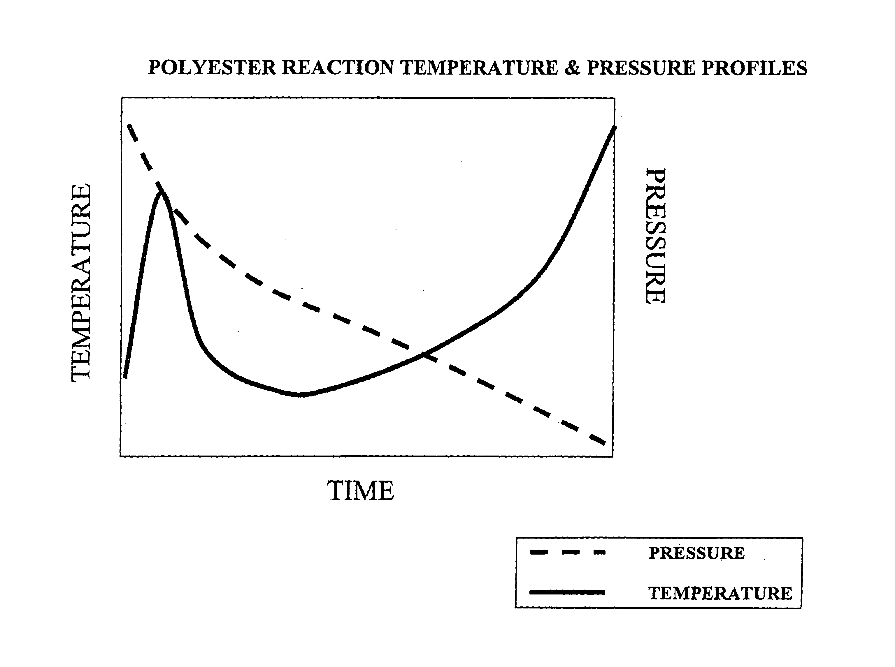
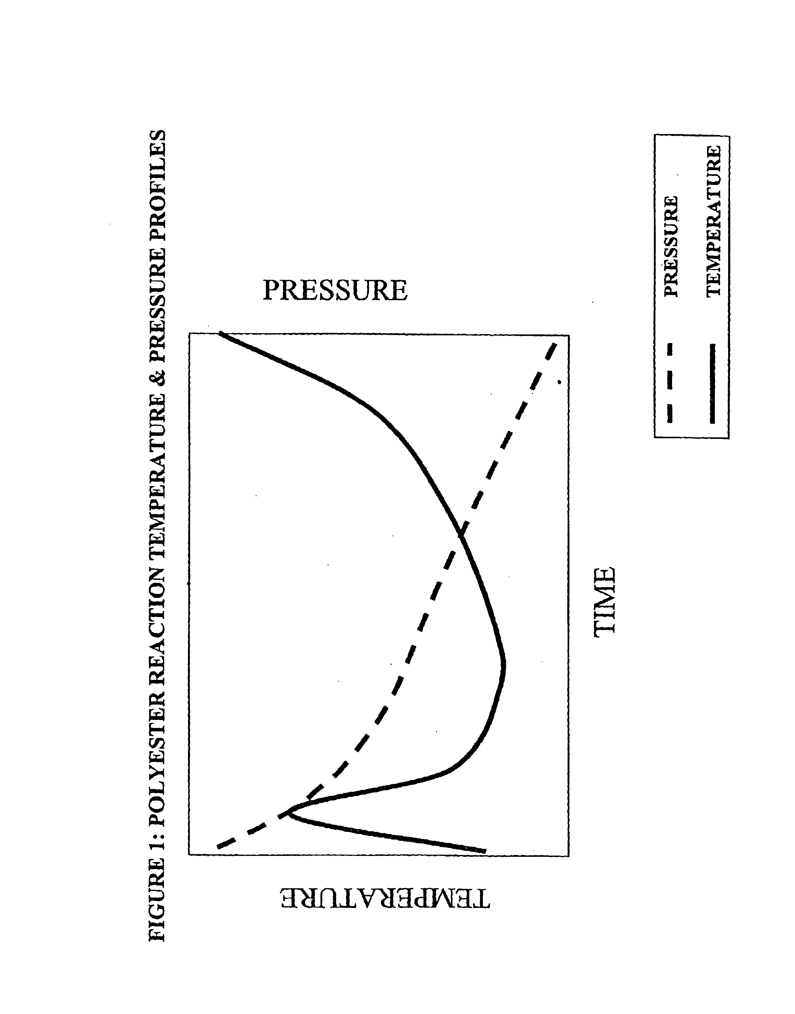
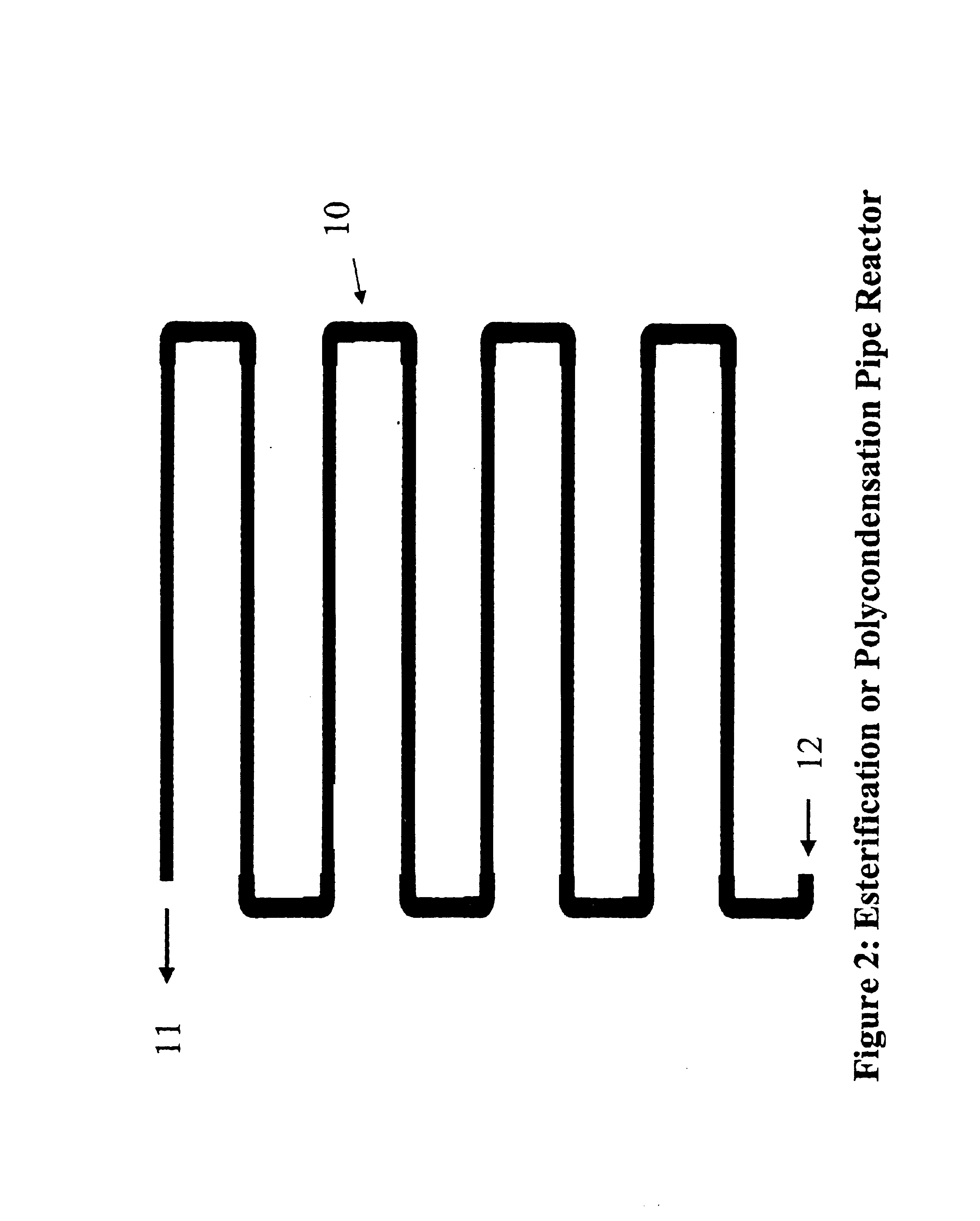
Polyester process using a pipe reactor
a technology of polyethylene and pipe reactor, which is applied in the direction of separation processes, liquid degasification, transportation and packaging, etc., can solve the problems of affecting the flow rate of fluids, too many heating coils, and insufficient space between coils, so as to achieve the effect of controlling the interface by controlling the reactive volume and difficult to control the fluid velocity
- Summary
- Abstract
- Description
- Claims
- Application Information
AI Technical Summary
Benefits of technology
Problems solved by technology
Method used
Image

Examples
second embodiment
In a second embodiment, the heat transfer media control system includes a first heat transfer media header through which the first heat transfer media stream is passed; a second heat transfer media header through which the second heat transfer media stream is passed; a first heat transfer media sub-loop through which the heat transfer media may be passed from the first header to the second header; a first control valve in fluid communication with the first header and the first sub-loop; and a second control valve in fluid communication with the first sub-loop and the second header. The pressure of the first heat transfer media stream within the first header being greater than the pressure of the second heat transfer media stream within the second header, and one or both of the control valves is used to selectively direct at least a portion of the first heat transfer media stream into the first sub-loop, using the pressure of the first heat transfer media stream, to pass the heat tra...
first embodiment
the described fluid delivery system therefore includes at least one delivery container positioned at a pump station, and at least one pump in fluid communication with the at least one delivery container, the at least one delivery container being in fluid communication with a valve train, the valve train being in fluid communication with the process plant pipe system. The fluid is selectively pumped directly from the at least one delivery container through the valve train and into the process plant pipe system in the absence of a fluid delivery feed and storage tank for otherwise receiving and storing the fluid from the at least one delivery container therein. Additionally, the system includes a second delivery container positioned at the pump station and a second pump in fluid communication with the second delivery container, each of the delivery containers and pumps, respectively, being in fluid communication with the valve train. The valve train is comprised of a plurality of sele...
example 1
Using ASPEN modeling, exemplary pipe lengths and heat exchange areas were calculated for a pipe reactor system for each of PET and PETG. The results are shown in Table 1 below.
TABLE 1EsterificationPolycondensationPipe Diameterin14121416PET Plant Pipeft73317751905LengthStage 1Stage 2PET Plant Heatft222002000Exchanger AreaPETG Plant Pipeft7975255680LengthStage 1Stage 2Stage 3PETG Plant Heatft222001900Exchanger Area
PUM
| Property | Measurement | Unit |
|---|---|---|
| pressure | aaaaa | aaaaa |
| hydrostatic pressure | aaaaa | aaaaa |
| boiling temperature | aaaaa | aaaaa |
Abstract
Description
Claims
Application Information