Fully integrated machinable profile based parametric solid modeler

a parametric solid modeler and fully integrated technology, applied in the field of solid modelers, can solve the problems of inability to compute the surface area and volume of parts, the inability to use the surface model to determine the volume of objects, and the difficulty of using the present modelers to represent all but the simplest material removal operations

Inactive Publication Date: 2005-03-01
SHAIKH MOHAMMAD SALIM
View PDF4 Cites 17 Cited by
  • Summary
  • Abstract
  • Description
  • Claims
  • Application Information

AI Technical Summary

Benefits of technology

In order to eliminate many of the limitations of the previous results, it is the objective of this research to develop a solid modeler specifically tailored for the material removal process associated with milling. The computer tool that will be describedis based on designing a part by sculpting the stock block,directly integrates a geometric modeler with the machining process,results in a fast, powerful and fully integrated solid model

Problems solved by technology

However, a wire frame model is an ambiguous model and, therefore, the surface area and volume of the part cannot be computed.
However, a surface model cannot be used to determine the volume of an object.
Solid modeling has gained wide acceptance because it provides an unambiguous model of an object However, because of the small set of primitives currently available it is very difficult to use the present modelers to represent any but the simplest material removal operations.
Consequently, machining information is not automatically available from a solid model; however, it can be extracted from it.
The difficulty with this method is that the machining information has to be extracted from the solid model after it is formed, which is a computationally difficult task.
Another drawback of this method is that the material removal information is extracted from the solid model and, therefore, the original part geometry is lost.
Secondly, no consideration is given to the machinability of a feature.
Using only these features in the design process limits the manufacturing to only that class of parts that can be

Method used


Image

  • Fully integrated machinable profile based parametric solid modeler
  • Fully integrated machinable profile based parametric solid modeler
  • Fully integrated machinable profile based parametric solid modeler

Examples


Embodiment Construction

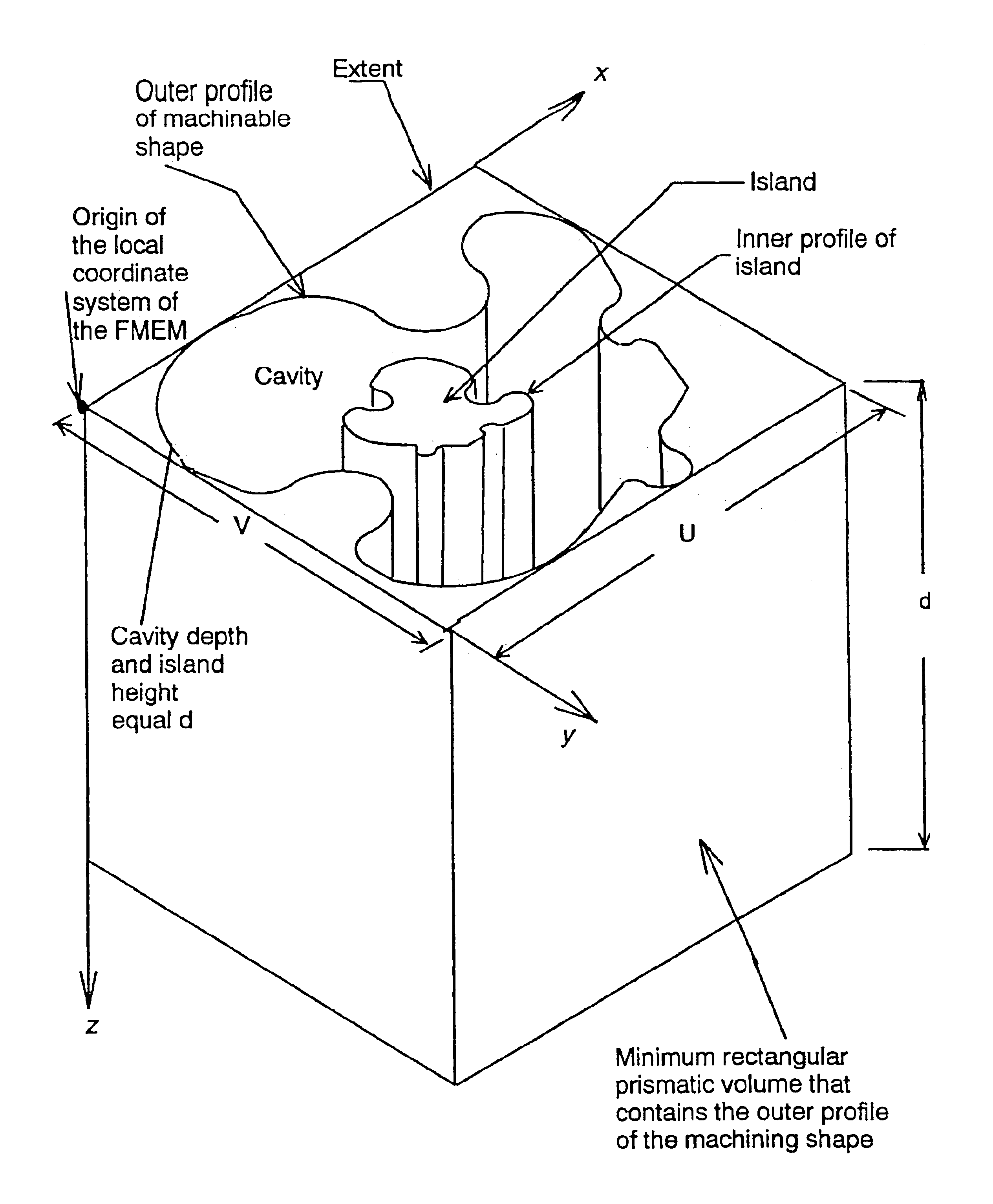
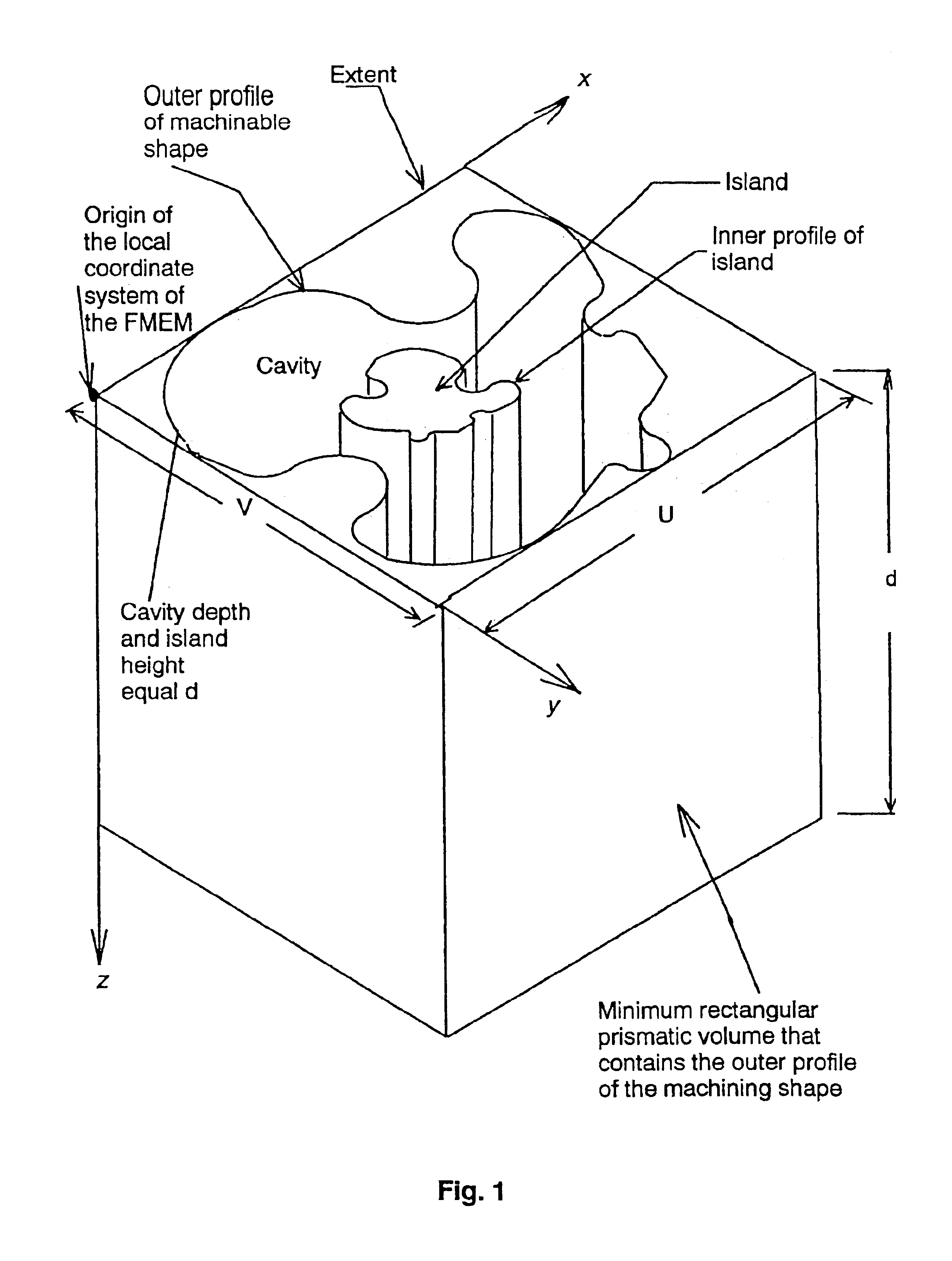
FIG. 1 illustrates the Fundamental Manufacturing Entity for Milling (FMEM), which is defined as the smallest solid volume that contains all the geometric information necessary to describe the shape of the volume of material removed during machining. The FMEM is a regular rectangular prismatic geometry containing a cavity and an island within the cavity. The shapes of the cavity and the island are each represented by very general profiles. The outer profile is contained within the smallest rectangular box of dimension U and V such that these edges are parallel to, and coincide with, the local coordinate axes x and y. The profile of the island can have any orientation with respect to the profile of the outer boundary, which in turn can have any orientation with respect to the coordinate axes x and y. The depth of the cavity and the depth of the prismatic block are equal. The profile can be applied to any of the six surfaces of the prismatic block.

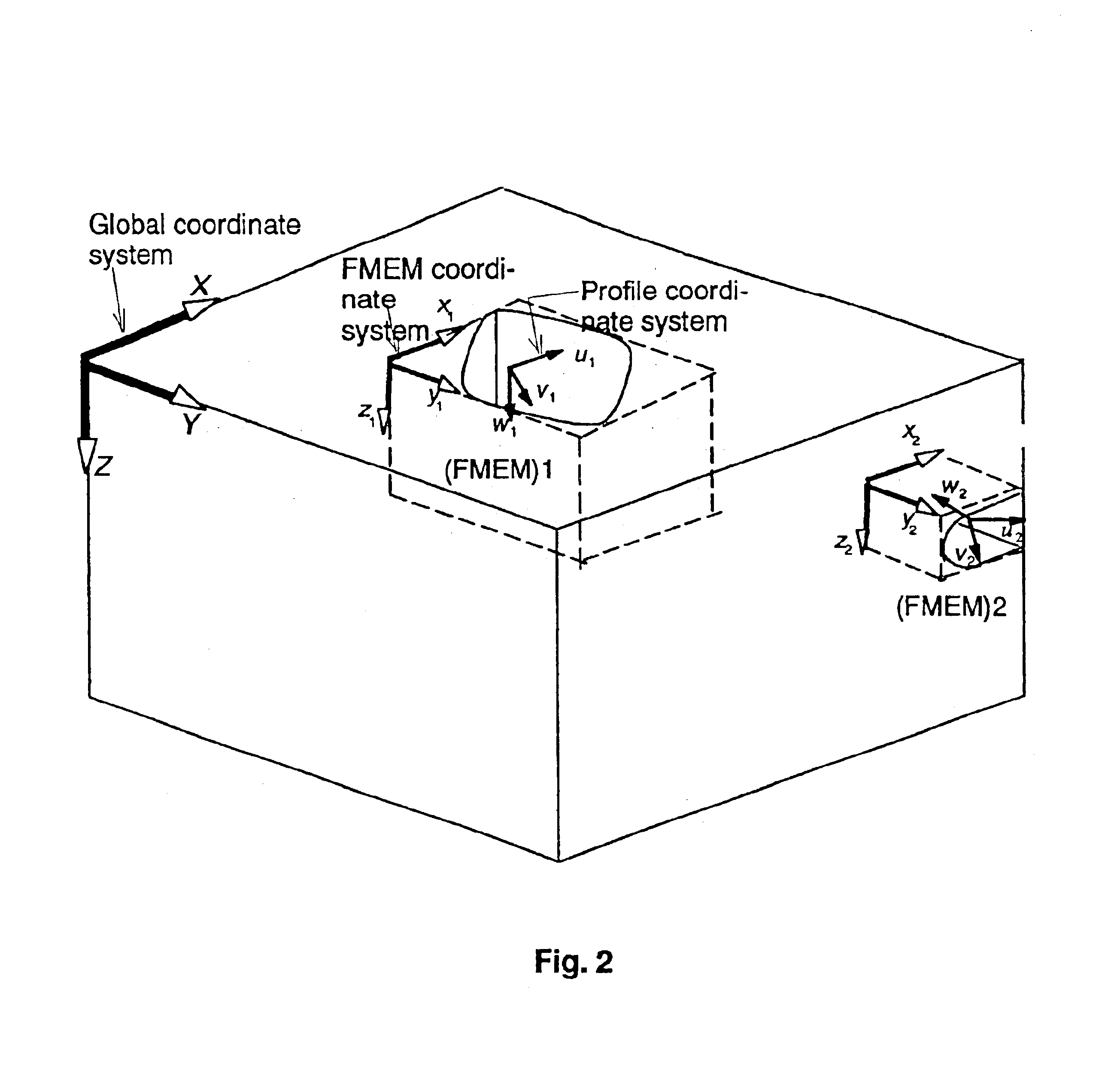
The three coordinate systems used in t...


PUM


Abstract

A solid modeler is provided which is specifically tailored for the material removal process associated with milling procedure. The solid modeler permits a part to be designed using only machinable profiles thereby constraining the designer to real world machinable operations. The method utilized by this solid modeler allows design manipulation of the edges and curves of a very general feature profile, thereby representing the milling process with the same degree of flexibility that the actual milling process has, and provides a means to create and store for use in the generation of other parts any combination of 2D and 3D features.

Description

BACKGROUND OF THE INVENTIONa) Field of the InventionThis invention provides a solid modeler specifically tailored for the material removal process associated with milling procedure, and that permits a part to be designed using only machinable profiles.b) Description of the Prior ArtObject modeling is a tool for a designer to display and verify his conceptual design on a computer screen. Earlier methods of object modeling were based on designing a part with 2D drawings. The designer provided the machining information using manufacturing symbols, tolerances, and dimensions. The completed design was turned over to a process planner. He reviewed 2D engineering drawings and integrated them to arrive at, in the case of milling, material removal information, which was then converted into a set of machining operations. This set of machining operations was then used to machine the part.With increased computing power available, methods were introduced whereby one could model a part as a 3D sh...

Claims


Application Information

Patent Timeline
IPC IPC(8): G06T17/10
CPCG06T17/10
Inventor SHAIKH, MOHAMMAD SALIM
Owner SHAIKH MOHAMMAD SALIM
Why Eureka
Try Eureka