Machining simulation method and apparatus

a simulation method and simulation method technology, applied in analogue computers, programme control, analog and hybrid computing, etc., can solve the problems of limited observation, too much or too little material being removed from the stock, and the testing process is expensive and time-consuming. , to achieve the effect of simulation, accurate operation, and fast operation

Inactive Publication Date: 2005-03-01
MACHINEWORKS
View PDF15 Cites 36 Cited by
  • Summary
  • Abstract
  • Description
  • Claims
  • Application Information

AI Technical Summary

Benefits of technology

It is an aim of at least preferred embodiments of the present invention to provide a method for simulating machining which operates quickly, accurately and with efficient use of memory.

Problems solved by technology

When a new machining process is developed a number of problems may occur, including, for example, unwanted collisions between the machine tool and the stock, and unexpected machining errors resulting in too much or too little material being removed from the stock.
However, this testing process is expensive and time consuming, and analysis is limited to observational techniques.
However, known methods suffer significant problems in terms of processing speed and memory requirements.

Method used


Image

  • Machining simulation method and apparatus
  • Machining simulation method and apparatus
  • Machining simulation method and apparatus

Examples


Embodiment Construction

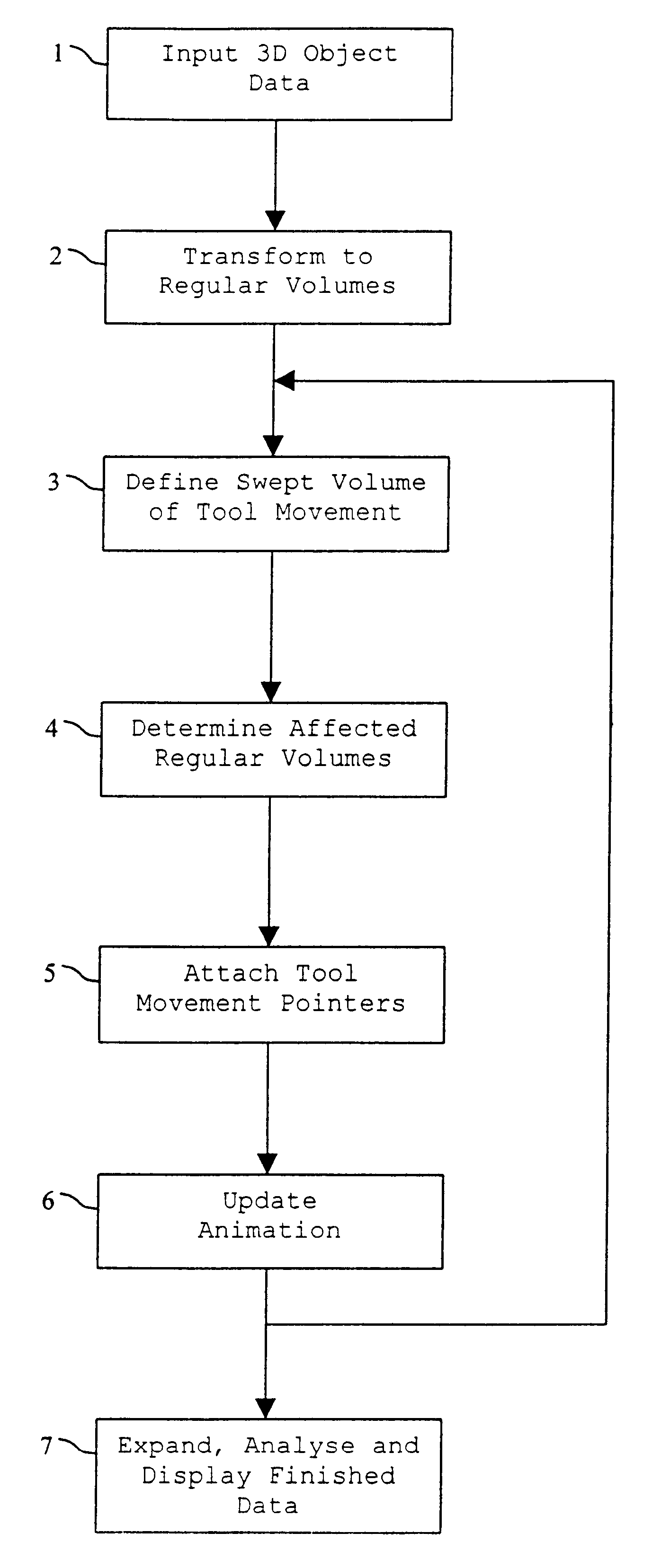
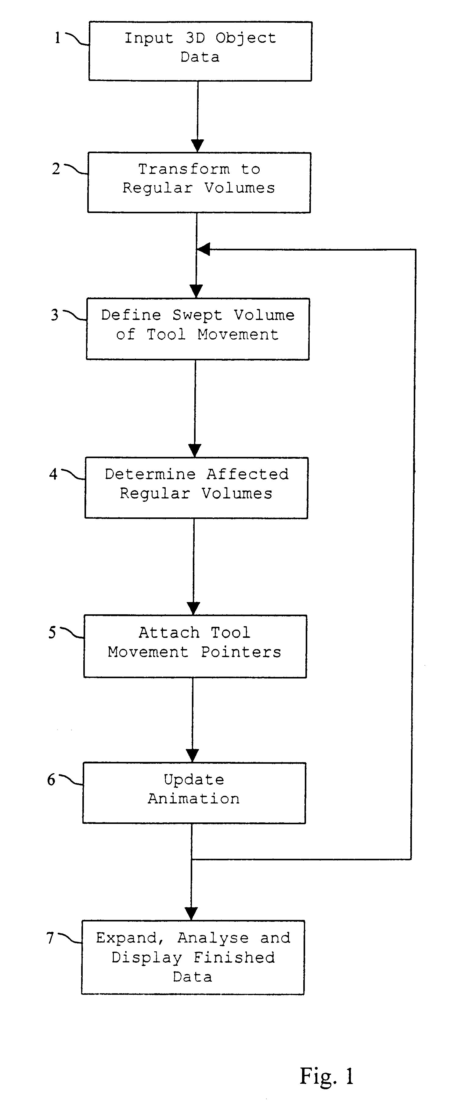
Referring to FIG. 1, a flowchart is shown giving an overview of the preferred embodiment of the machining simulation method.

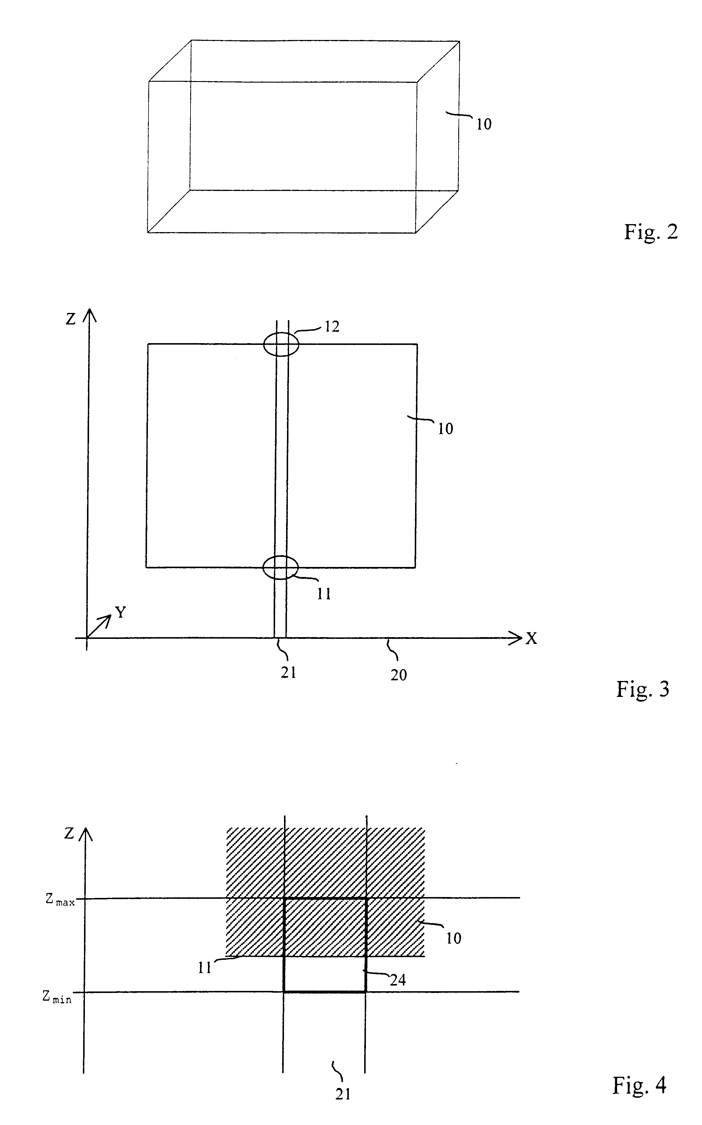
A 3D object dataset representing the raw stock is received at step 1. This 3D object dataset is transformed in step 2 to produce a modelling dataset. This modelling dataset will be termed an “extended voxel” format. In the modelling dataset the surface of the raw stock object is defined in terms of a large number of relatively small elements. Each of these small elements, termed herein “regular volumes”, is a small volume containing a small section of the surface of the stock object.

In step 3 a cut function is performed to determine a swept volume of a tool movement. The machining tool moves from a start position to an end position. The machining tool is known to have a predetermined size and configuration and the path of the tool from the start point to the end point readily determines the swept volume relating to that tool movement.

In step 4 the parts of the ...


PUM


Abstract

A machining simulation method using a plurality of equally sized regular volumes such as cubes to represent the surface of a raw stock object at a relatively low resolution. Each regular volume contains a reference to that portion of the original stock surface falling within that regular volume. The regular volumes affected by the swept volume of each tool movement are readily determined, and a pointer to that tool movement is added to each affected regular volume. The finished data may be expanded in detail at any portion of interest to create fully realised surface geometry with full boundary information by combining the original stock surface and the relevant surfaces of each tool movement. The original stock object may be displayed using the low-resolution regular volumes from any convenient view point, and may be animated in real time to show the effects of each tool movement.

Description

FIELD OF THE INVENTIONThe present invention relates in general to the field of computer graphics and simulation methods for representing solid objects, and in particular to a method for simulating and evaluating a machining process.BACKGROUND TO THE INVENTIONIn the field of numerically controlled (NC) machining a machine tool repeatedly passes over a stock. Commonly, a milling tool is used to mill the surface of the stock, thereby removing a small volume of the stock. A typical NC machining process involves of the order of 250,000 individual tool movements, and sometimes many more.When a new machining process is developed a number of problems may occur, including, for example, unwanted collisions between the machine tool and the stock, and unexpected machining errors resulting in too much or too little material being removed from the stock. Traditionally a new machining process is verified by performing a test milling on a soft, inexpensive material. However, this testing process is...

Claims


Application Information

Patent Timeline
Patent Type & Authority Patents(United States)
IPC IPC(8): G05B19/4069G05B19/406G06G7/48G06G7/00G06F19/00
CPCG05B19/4069
Inventor EDWARDS, WILLIAM RICHARD VICTORLIN, FENQUIAN
Owner MACHINEWORKS
Why Eureka
Try Eureka