Supercharge Your Innovation With Domain-Expert AI Agents!

Oil removing device for cleaning pipes that are present in the form of coils

a technology of oil removal device and cleaning pipe, which is applied in the direction of hair comb, drying solid materials, drying machines, etc., can solve problems such as leakage, and achieve the effect of simple and gas-tight connection of coils

Inactive Publication Date: 2005-03-08
OTTO JUNKER GMBH
View PDF3 Cites 0 Cited by
  • Summary
  • Abstract
  • Description
  • Claims
  • Application Information

AI Technical Summary

Benefits of technology

The problem of the present invention is to provide an oil removal device which allows simple and gas-tight connection of coils to a gas supply device.
Furthermore, the device according to the present invention may be implemented so that the two pipe ends of each coil are each connected via a flexible coupling to the pipeline which supplies and removes the gas. Therefore, the connection of a coil to the gas supply line and gas removal line is significantly simplified, since geometric tolerances of the external shape of the coil may be compensated for through the flexible couplings.
Furthermore, the device according to the present invention may be implemented so that the sections of the gas supply line and the gas removal line neighboring the connection head are mounted pivotably to adjust for any tolerances as the gas line and connection head meet. In this way, the seal to the connection head in the furnace chamber may be made even more reliable.
Furthermore, the device according to the present invention may be implemented so that the sections of the gas supply line and the gas removal line neighboring the connection head are implemented as axially flexible. In this way, the tolerances arising in the axial direction during positioning of the connection head in the furnace chamber are compensated without the stand being displaced through the incident pressure.
Finally, the device according to the present invention may be implemented so that the pipeline for the gas to be removed has multiple channels which are separate from one another, which each communicate with the outlet of a pipe of a specific coil. Vice versa, the pipeline for the gas to be supplied may also have multiple channels which are separate from one another, which each communicate with an inlet of a pipe of a specific coil. This allows measurement and regulation of the gas flow through a specific coil.

Problems solved by technology

A great disadvantage of the device described results from the gas supply and gas removal connections, which are positioned separately from one another and are independent of one another.
In the event of high contact pressure, there is therefore the danger that the support stand will be displaced or deformed by the mechanical forces introduced via the connection device, so that leaks may arise.

Method used


Image

  • Oil removing device for cleaning pipes that are present in the form of coils
  • Oil removing device for cleaning pipes that are present in the form of coils
  • Oil removing device for cleaning pipes that are present in the form of coils

Examples


Embodiment Construction

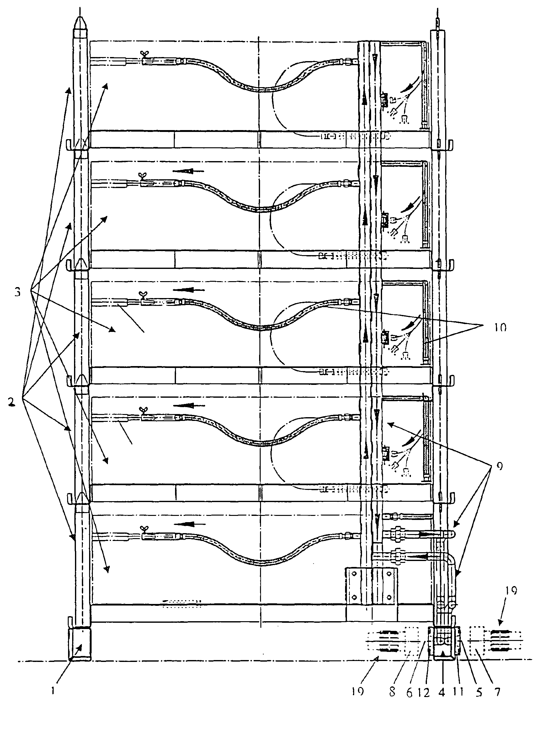
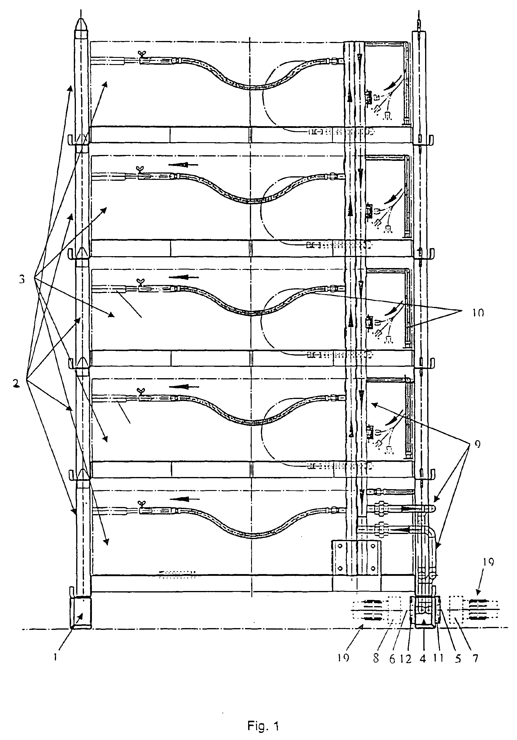
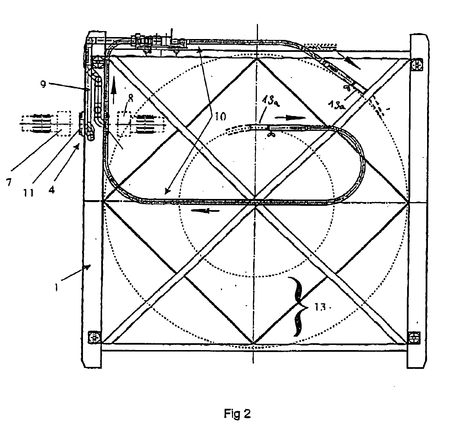
Referring to FIGS. 1-3, a stand 1 (FIG. 1) has attachments 2 positioned on top of one another, which each have a space 3 for receiving coils. A connection head 4 having a gas inlet opening 5 and an opposing gas outlet opening 6 is integrated into the stand 1. Ends 7 and 8 of the gas supply line 15 and gas removal line 16 connected to the connection head 4 are shown with dashes. The gas inlet opening 5 and gas outlet opening 6 are aligned axially and opposite to the openings 5, 6 of the connection head 4. It may be clearly seen that the openings of the connection parts 7, 8 of the gas supply line 15 and gas removal line 16 and the inlet and outlet openings 5, 6 of the connection head 4 are aligned on one axis, so that the connection parts 7, 8 are to be moved along the axis in order to produce a connection to the connection head 4. FIG. 2 shows a lower part of the stand 1, in which the connection head 4 is integrated in such a way that it comprises a connection part 11 provided for g...


PUM

PropertyMeasurementUnit
Flexibilityaaaaaaaaaa

Abstract

An oil removing device for cleaning pipes that are present in the form of coils in a furnace that accommodates and heats the pipes, with or without associated cooling zone, has a gas guiding device for feeding a scavenging gas to or removing it from the pipes. The gas guiding device is provided with connections for detachably and sealingly linking with a gas feed line and a gas discharge line. Ends of every pipe are separately connected to one and the same connecting head that has a gas inlet and a gas outlet opening the axially aligned therewith. The end of the gas feed line and the end of the gas discharge line are opposite each other and can be displaced along with the gas inlet opening and / or the gas outlet opening while sealingly connected.

Description

BACKGROUNDThe present invention relates to an oil removal device for cleaning pipes provided in the form of coils, having a furnace which receives and heats the pipes, with or without an assigned cooling zone, and a gas guiding device for introducing and removing scavenging gas into the pipes and / or out of the pipes, the gas guiding device having means for detachable, tight connection to a gas supply line on one side and a gas removal line on the other side.An oil removal device is known from European Patent Application 0659907 B 1. In the device described there, the coil is heated in a furnace chamber and a gas is introduced and removed via a gas supply line to clean the inside of a pipe. In this case, the connection to the ends of the pipe to be cleaned is produced via two couplings, which are each attached to a pull and push rod and are moved toward the corresponding counterparts independently from one another and at diametrically opposing sides of the furnace chamber. This conne...

Claims


Application Information

Patent Timeline
IPC IPC(8): B21C43/00C23G5/00C21D9/08C21D1/74F28G1/16C23G3/04F28G15/04
CPCB21C43/00C23G5/00C21D9/08C21D1/74
Inventor JOHNEN, WILLIJONES, GLYNN
Owner OTTO JUNKER GMBH
Features
  • R&D
  • Intellectual Property
  • Life Sciences
  • Materials
  • Tech Scout
  • Unparalleled Data Quality
  • Higher Quality Content
  • 60% Fewer Hallucinations
Learn More