
Directional sliding pendulum seismic isolation systems and articulated sliding assemblies therefor

a technology of seismic isolation and directional sliding, which is applied in the direction of machine supports, shock-proofing, other domestic objects, etc., can solve the problems of affecting the installation effect of the fixed support pier b, the diameter of the dish becomes even larger, and the structure designed according to the strength design principle tends to experience severe damage or excessive deformation, so as to achieve easy installation

Inactive Publication Date: 2005-03-08
SEOUL NAT UNIV R&DB FOUND
View PDF13 Cites 25 Cited by
  • Summary
  • Abstract
  • Description
  • Claims
  • Application Information

AI Technical Summary

Benefits of technology

It is, therefore, an object of the present invention to provide a sliding pendulum seismic isolation system having a new configuration, which can be easily installed without limitations in an installation area.
Preferably, in the sliding assembly, friction-reducing materials are coated on the surface of the slider core to reduce a friction between the slider core and the sliding channel and a friction between the slider core and the slider support.

Problems solved by technology

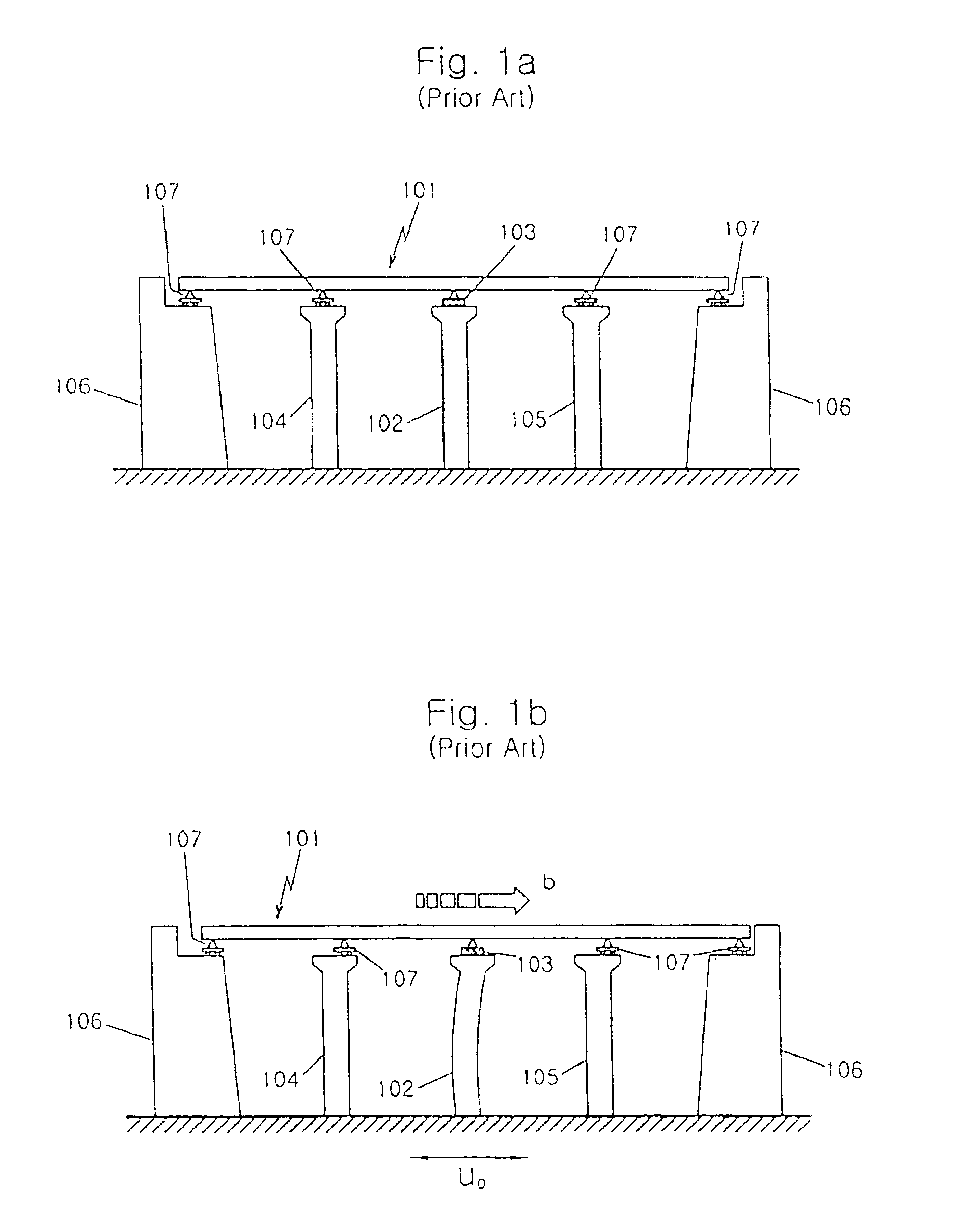
If an excessive seismic load is applied to the fixed support pier 102, the bridge itself as well as the fixed support 103 of the fixed support pier 102 will be seriously damaged, consequently resulting in possible failure of the fixed support pier 102.
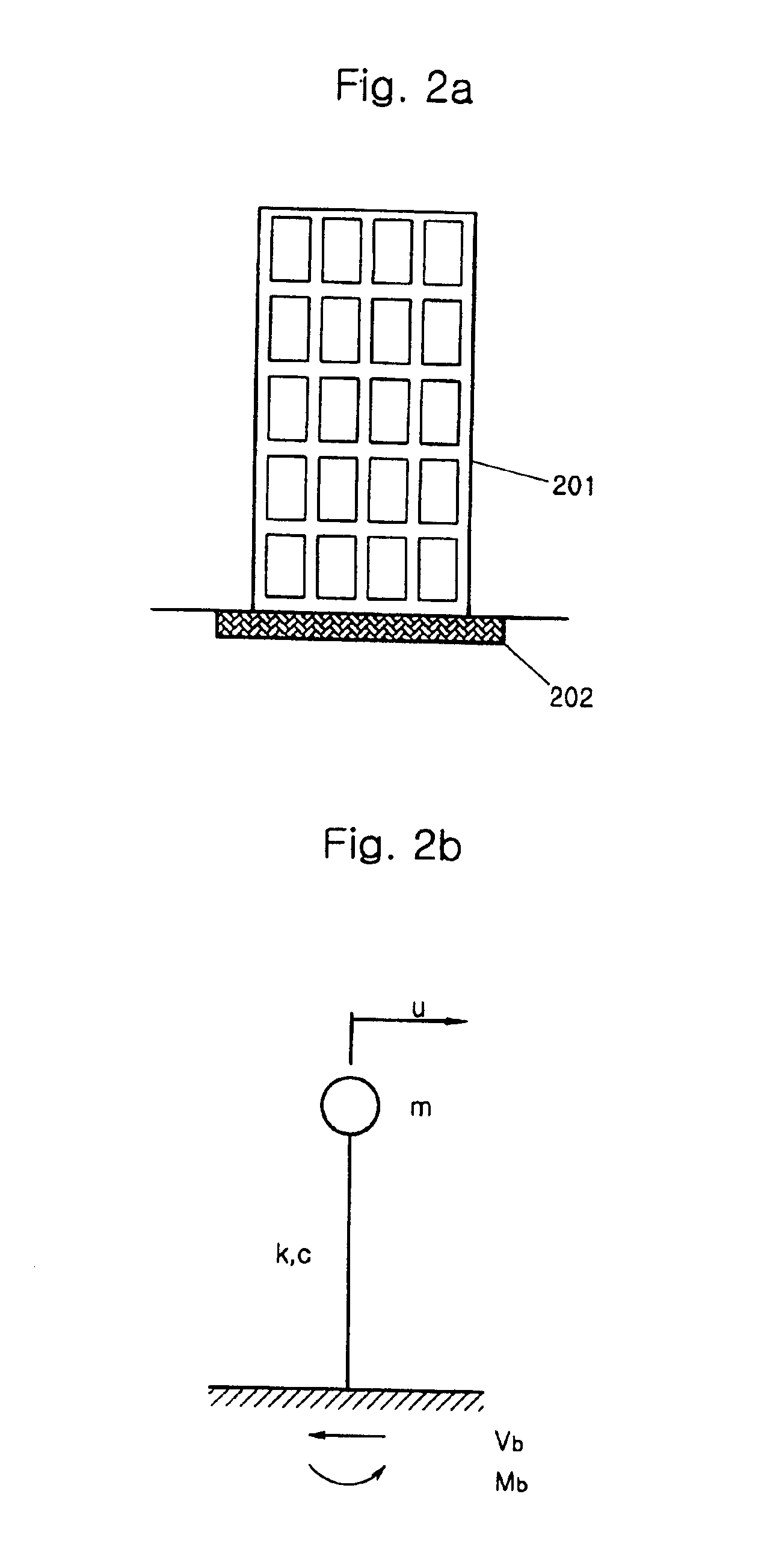
However, the structures designed according to this strength design principle tend to experience severe damage or excessive deformation in the event of very strong earthquake even though they may not collapse.
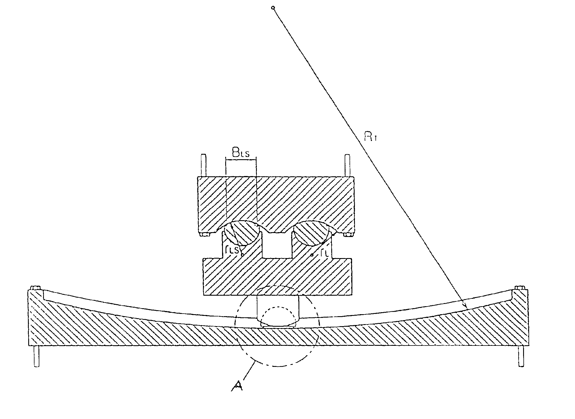
However, the sliding pendulum seismic isolation system used presently has a structure that a slider moves on a dish having a concave surface, and therefore if the seismic isolating period becomes longer, the diameter of the dish becomes even larger.
In the case of bridges, generally, an area to install a seismic isolator on a pier or an abutment is extremely restricted.
Therefore, a long span bridge requiring the seismic isolating period of a long-term has a difficulty in using the conventional sliding pendulum seismic isolation system of the dish type.

Method used


Image

  • Directional sliding pendulum seismic isolation systems and articulated sliding assemblies therefor
  • Directional sliding pendulum seismic isolation systems and articulated sliding assemblies therefor
  • Directional sliding pendulum seismic isolation systems and articulated sliding assemblies therefor

Examples


Embodiment Construction

The present invention will now be described in detail in connection with preferred embodiments with reference to the accompanying drawings.

FIG. 4 shows a schematically perspective view of an embodiment of bi-directional sliding pendulum seismic isolation systems according to the present invention.

As shown in FIG. 4, the bi-directional sliding pendulum seismic isolation system 1 according to the present invention includes a lower sliding plate 10 forming a sliding path in the first direction, an upper sliding plate 20 forming a sliding path in the second direction, and a sliding assembly 30 sliding in the two directions and performing the pendulum motion between the lower sliding plate 10 and the upper sliding plate 20.

FIGS. 5a through 5c show the lower sliding plate 10 in more detail. FIG. 5a is a perspective view of the lower sliding plate 10, and FIGS. 5b and 5c are views taken along the lines C—C and D—D in FIG. 5a. As shown in FIG. 5a, the lower sliding plate 10 has lower slidin...


PUM


Abstract

A bi-directional sliding pendulum seismic isolation system for reducing seismic force acting on a structure by sliding pendulum movements, each system comprising a lower sliding plate forming a sliding path in a first direction, an upper sliding plate forming a sliding path in a second direction, and a sliding assembly for reducing the seismic force of the structure by performing a pendulum motion by sliding along the lower and upper sliding plates.

Description

FIELD OF THE INVENTION1. Field of the InventionThe present invention relates to directional sliding pendulum seismic isolation systems and articulated sliding assembly therefor, and more particularly, to directional sliding pendulum seismic isolation systems and articulated sliding assemblies therefore, that can reduce seismic load applied to structures, such as bridges or general buildings, through directional pendulum motion and frictional sliding.2. Description of the Related ArtRecently, multi-span continuous bridges are widely used. In general, such a multi-span continuous bridge is designed to have a single fixed point in the longitudinal direction of the bridge. FIG. 1a shows an example of the conventional multi-span continuous bridge. In the conventional 4-span continuous bridge, a fixed support 102 is installed on a fixed support pier 103, which is located in the middle of the 4-span continuous bridge, to restrict the longitudinal movement of the superstructure 101 of the b...

Claims


Application Information

Patent Timeline
Patent Type & Authority Patents(United States)
IPC IPC(8): E04H9/02
CPCE04H9/023
Inventor KIM, JAE KWAN
Owner SEOUL NAT UNIV R&DB FOUND
Learn More