Liquid spray device

a technology of liquid atomizing device and spray device, which is applied in the direction of spraying device, spraying nozzle, spraying apparatus, etc., can solve the problems of high cost, high manufacturing aspect, reliability and operability, etc., and achieves the effect of improving anticorrosion, reducing time and labor costs, and sufficient strength

Inactive Publication Date: 2005-03-08
OMRON HEALTHCARE CO LTD
View PDF14 Cites 84 Cited by
  • Summary
  • Abstract
  • Description
  • Claims
  • Application Information

AI Technical Summary

Benefits of technology

Furthermore, if the mesh member is formed using a NiPd alloy by electroforming, a density of the fine pores can be further raised while keeping a sufficient strength with improvement on anticorrosiveness.

Problems solved by technology

In a liquid atomizing apparatus having the above liquid atomizing construction, however, a necessity exists for providing fine water suction holes for sucking up the chemical liquid into the pipe with an accompanying problem of much expenses in time and labor, and therefore increase in cost, in manufacturing aspect.
Therefore, problems have also arisen in reliability and operability in addition to a fault of complexity in feed means leading to high cost.
In the mean time, in a case where any of the above liquid atomizing constructions is adopted, while the mesh member is pressed onto the end surface of the distal end of the horn oscillating member by a force with a proper magnitude, a chemical liquid gathered in the proximity of the mesh member is leaked out onto the front surface and the periphery of the mesh member, and the leaked chemical liquid contaminates the outer surface of the apparatus and is hardened thereon to thereby hinder oscillation of the mesh member, thus having resulted in problems such as poor atomizing performance.
What's worse, a need arises for carefulness so as to limit a chance of excessive inclination of the apparatus to the lowest probability, which has made handling of the apparatus difficult.
Mesh members 80A and 80B are important factors in determination of an atomizing performance of a liquid atomizing apparatus, but acting as a main cause for clogging and degradation in performance of the mesh.

Method used


Image

  • Liquid spray device
  • Liquid spray device
  • Liquid spray device

Examples


Embodiment Construction

Description will be given of an embodiment based on the present invention below.

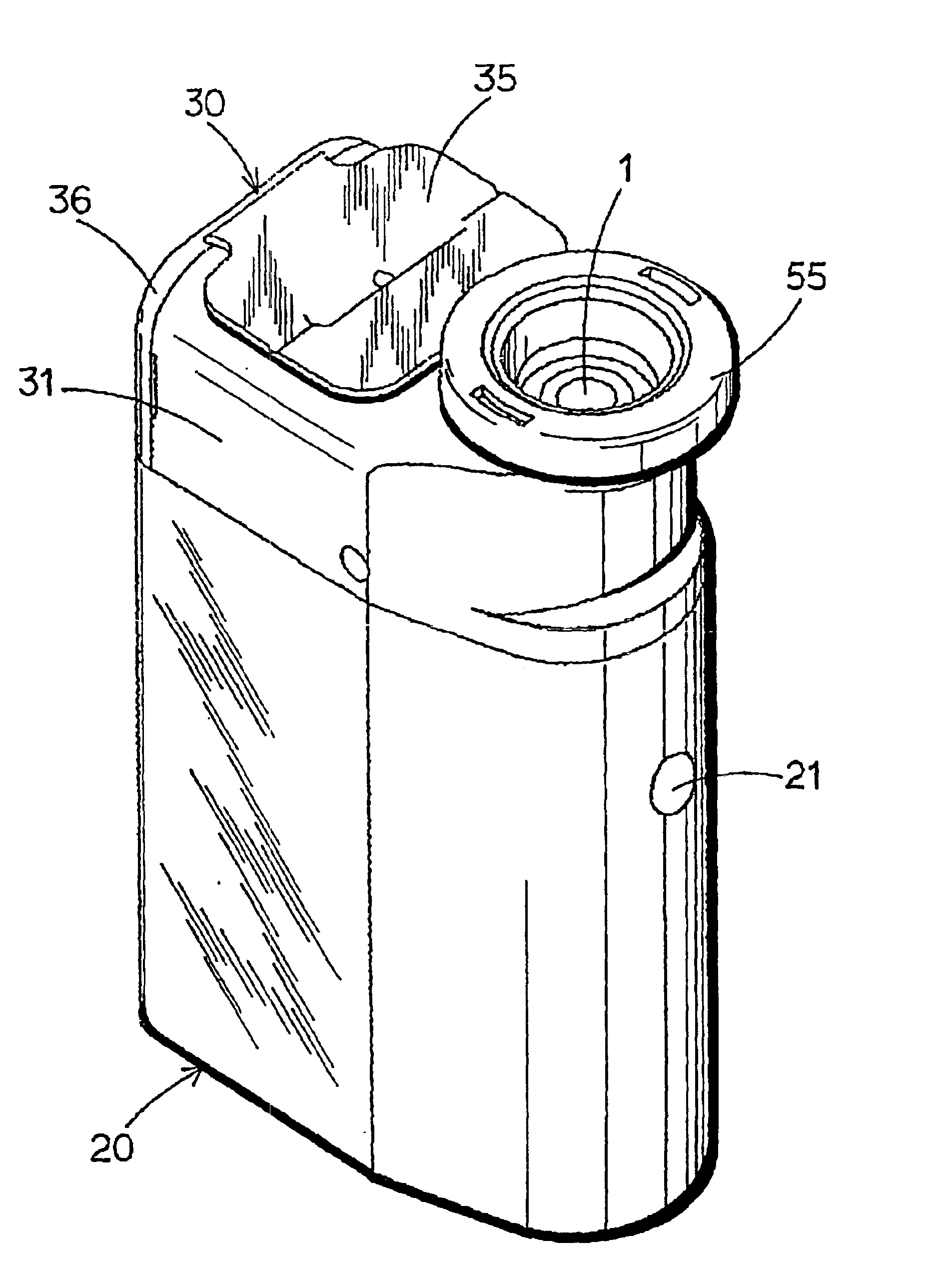
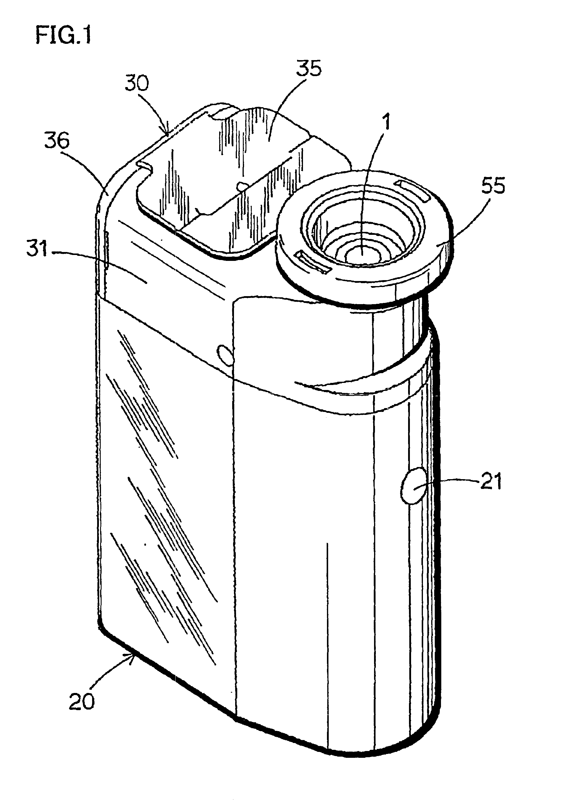
First of all, the description gets started with a configuration in appearance of a liquid atomizing apparatus relating to the embodiment based on the present invention with reference to FIG. 1. The liquid atomizing apparatus includes: not only a power supply switch 21 but also a body section 20 having a built-in battery and electrical circuitry therein and a bottle unit 30 attached to the body section 20 in a demountable manner.

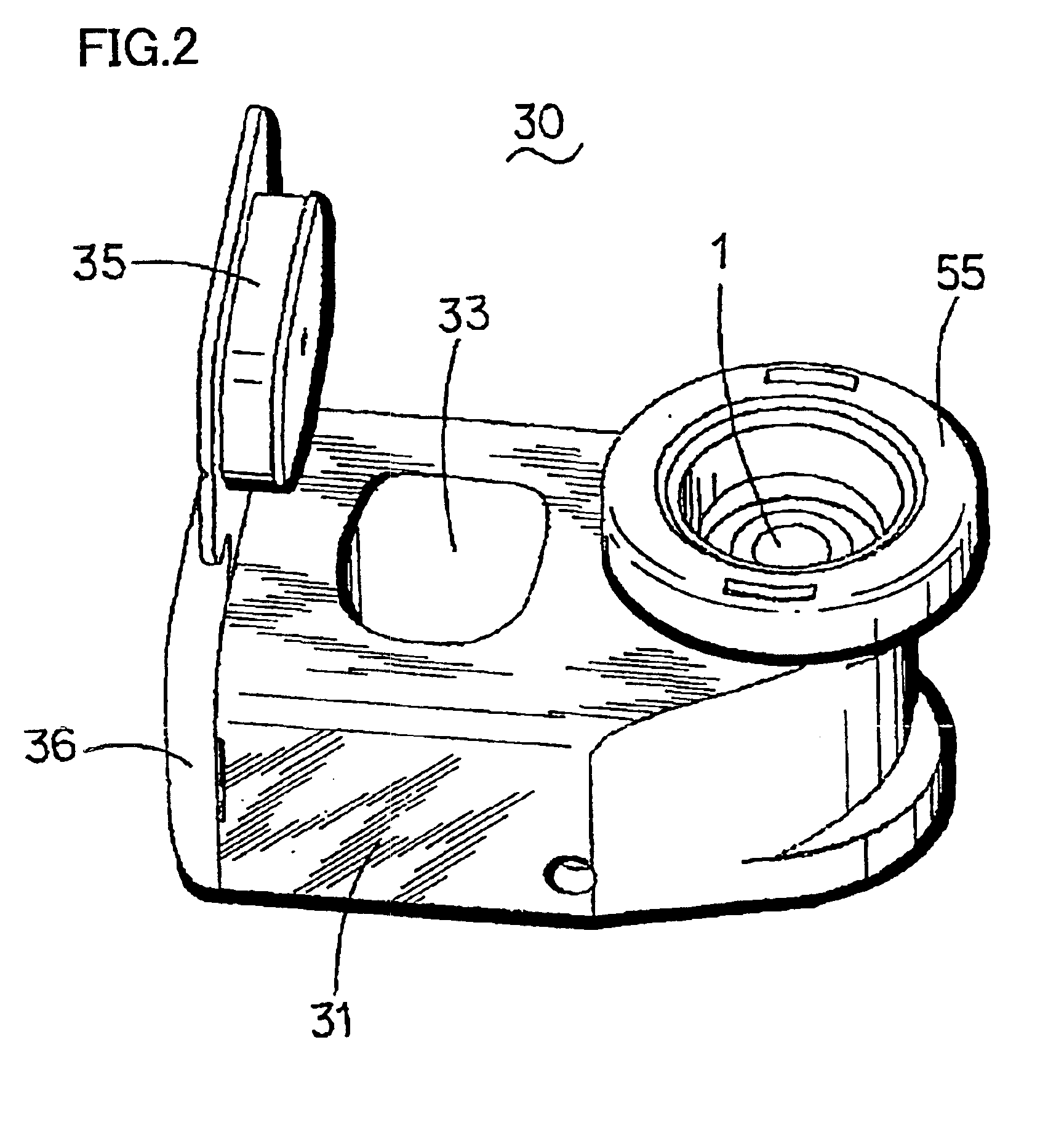
Bottle unit 30 has a construction as shown in FIG. 2 (perspective view), FIG. 3 (longitudinal sectional view), FIG. 4 (partially cut-away perspective view of a main part), FIG. 5 partially cut-away perspective view of a main part in an expanded configuration) and FIG. 6 (enlarged longitudinal sectional view of a main part).

Bottle unit 30 is provided with: a liquid reservoir section (bottle section) 31 reserving a liquid (a chemical liquid) L; an oscillation source (a horn oscillat...


PUM


Abstract

A bottle unit (30) of a liquid atomizing apparatus is provided with: a bottle section (31) reserving a chemical liquid (L); a horn oscillating member (40) to whose a distal end the liquid (L) in the bottle section (31) is fed; and a mesh member (1) having a number of fine pores (2), and mounted to an end surface of the distal end (41) of the horn oscillating member (40) in contact therewith. The bottle section (31) is constituted of a large capacity section (B) and a small capacity section (b) in communication with the large capacity section (B) through an opening (32), and opposing to the distal end (41) of the horn oscillating member (40). The small capacity section (b) is formed such that the liquid (L′) therein is in contact with a point in the proximity of the contact section between the distal end (41) of the horn oscillating member (40) and the mesh member (1). With such a construction adopted, there can be provided a liquid atomizing apparatus that is obtained at a low cost with not only increased reliability but enhanced durability, and whose operations such as maintenance can be performed with simplicity and convenience without a necessity for a special liquid feed means.

Description

TECHNICAL FIELDThe present invention relates to a liquid atomizing apparatus, and more particularly to an ultrasonic mesh type liquid atomizing apparatus atomizing a liquid using a horn oscillating member and a mesh member.BACKGROUND ARTA conventional ultrasonic type liquid atomizing apparatus has a liquid atomizing construction as an example, as shown in FIG. 17. A liquid atomizing construction shown herein includes: a liquid reservoir section (a bottle) 70 reserving a liquid (a chemical liquid) L; an ultrasonic pump (a horn oscillating member) 77; and a mesh member 80. Horn oscillating member 77 is constructed of: a pipe 74 having liquid-suction through holes (water suction holes) 73 extending along an axial direction, and communicating from a lower end 71 located in bottle 70 to an opening provided at the top end 72 located outside bottle 70; and two annular oscillating members 75 and 76 mounted to pipe 74. Mesh member 80 is mounted to pipe top end 72 in contact therewith using a...

Claims


Application Information

Patent Timeline
Patent Type & Authority Patents(United States)
IPC IPC(8): B05B17/04B05B17/06
CPCB05B17/0623B05B17/0638B05B17/063B05B17/06
Inventor TERADA, TAKAOASAI, KEIARAI, MASATOITOH, SHINICHITANAKA, SHINYAOSUGA, MASASHITAKAHASHI, TOSHIJI
Owner OMRON HEALTHCARE CO LTD
Why Eureka
Try Eureka