Compressed gas utilization system and method with sub-sea gas storage

a gas storage system and compressed gas technology, applied in the direction of container discharging methods, special purpose vessels, container filling under pressure, etc., can solve the problems of sub-sea gas storage facilities susceptible to earthquake damage, transmission costs, losses and related expenses, and severe limits on site location

Inactive Publication Date: 2005-03-08
DRESSER RAND CO
View PDF14 Cites 47 Cited by
  • Summary
  • Abstract
  • Description
  • Claims
  • Application Information

AI Technical Summary

Problems solved by technology

This severely limits the site location due to the dependence on an acceptable geology for underground storage location.
Also, the underground storage facility is usually located a considerable distance from the power generation or power consumption areas, resulting in transmission costs, losses and related expenses.
Furthermore, underground storage facilities are susceptible to earthquake damage.

Method used


Image

  • Compressed gas utilization system and method with sub-sea gas storage
  • Compressed gas utilization system and method with sub-sea gas storage

Examples


Embodiment Construction

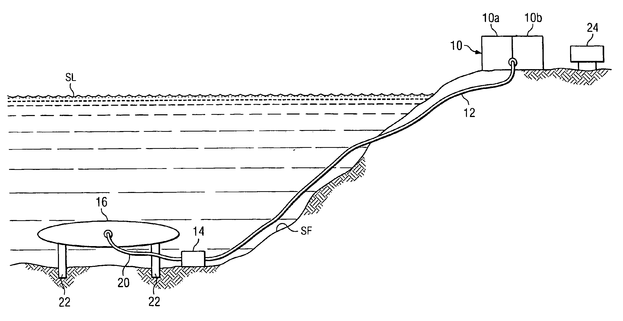
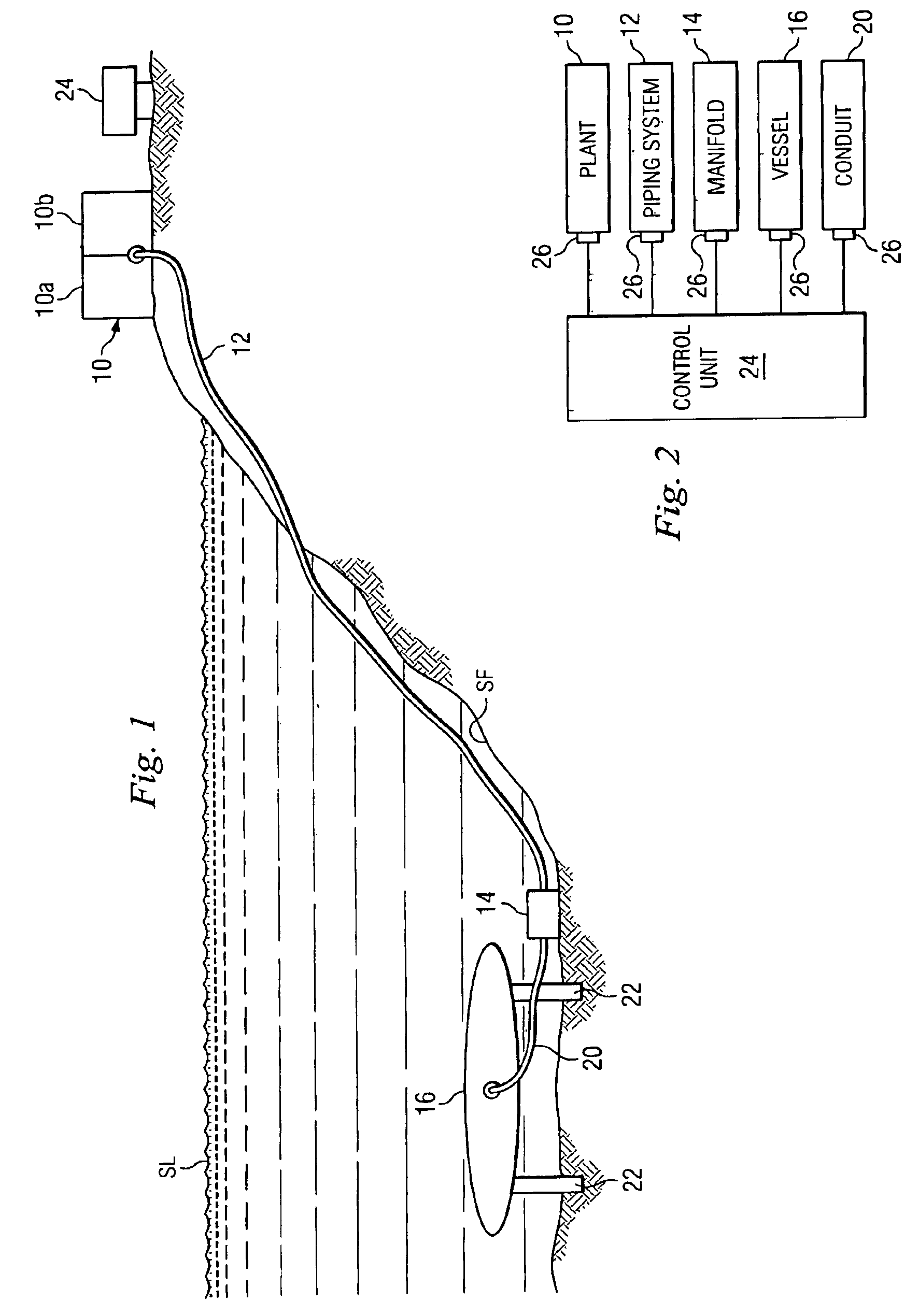
FIG. 1 depicts a system according to an embodiment of the invention which includes a plant 10 having a compression side 10a that includes a conventional motor-driven compression train and associated equipment (not shown) for compressing a gas, such as ambient air. The plant 10 also has an expansion side 10b in which the compressed gas is expanded through a conventional expansion train that includes high pressure and low pressure turbines that drive an electrical power generator to generate electrical power. It is understood that during operation of the expansion side 10b of the plant 10, the gas can be burned with fuel to improve the efficiency of the plant. Since the turbines, the compression and expansion trains, and the power generator are conventional they are not shown nor will they be described in further detail.

The plant 10 is located on the ground surface in the vicinity of a coastline near an adjacent water source such as a lake, sea, or ocean (hereinafter referred to as “s...


PUM


Abstract

A system and method utilizing compressed gas according to which the gas is compressed at a location above ground and transported to an underwater location. The gas is stored at the underwater location and later returned from the underwater location to the above-ground location for utilization as energy.

Description

BACKGROUNDThis invention relates to a compressed gas utilization system and method and, more particularly, to such a system and method in which the compressed gas is stored in a sub-sea environment and later utilized as energy.Compressed air energy storage (CAES) systems are generally known, and are for the purpose of storing energy, in the form of compressed gas, and later utilizing this stored potential energy for such purposes as the generation of electrical power. Typically, the CAES systems use electrical power purchased at low cost during off-peak periods to compress gas for storage. During periods of peak power demand, the potential energy in the stored gas is used to produce electrical power, which may be sole at a premium rate.These systems can be used in a stand-alone mode for generating electrical power connected in a power grid, or they can be used with a conventional electrical power generating plant connected in a power grid, or the like. In the latter case, the power ...

Claims


Application Information

Patent Timeline
Patent Type & Authority Patents(United States)
IPC IPC(8): F17C7/00F17C13/00F17C5/00F17C13/02F17C5/06F17C3/00F17C1/00F17C1/16
CPCF17C1/16F17C5/06F17C7/00F17C13/025F17C13/028F17C3/005F17C2270/0581F17C2201/0176F17C2201/052F17C2201/054F17C2203/0617F17C2203/0658F17C2203/0685F17C2205/0142F17C2205/0146F17C2205/0184F17C2205/0326F17C2221/031F17C2221/033F17C2223/0123F17C2223/035F17C2223/036F17C2225/0123F17C2225/035F17C2225/036F17C2227/0157F17C2227/0362F17C2250/032F17C2250/0426F17C2250/043F17C2250/0443F17C2250/0469F17C2260/046F17C2270/0131
Inventor WEBSTER, BRIAN Y.COLLINS, CHRISTOPHER D.MOODY, JR., JAMES A.
Owner DRESSER RAND CO
Why Eureka
Try Eureka