An air
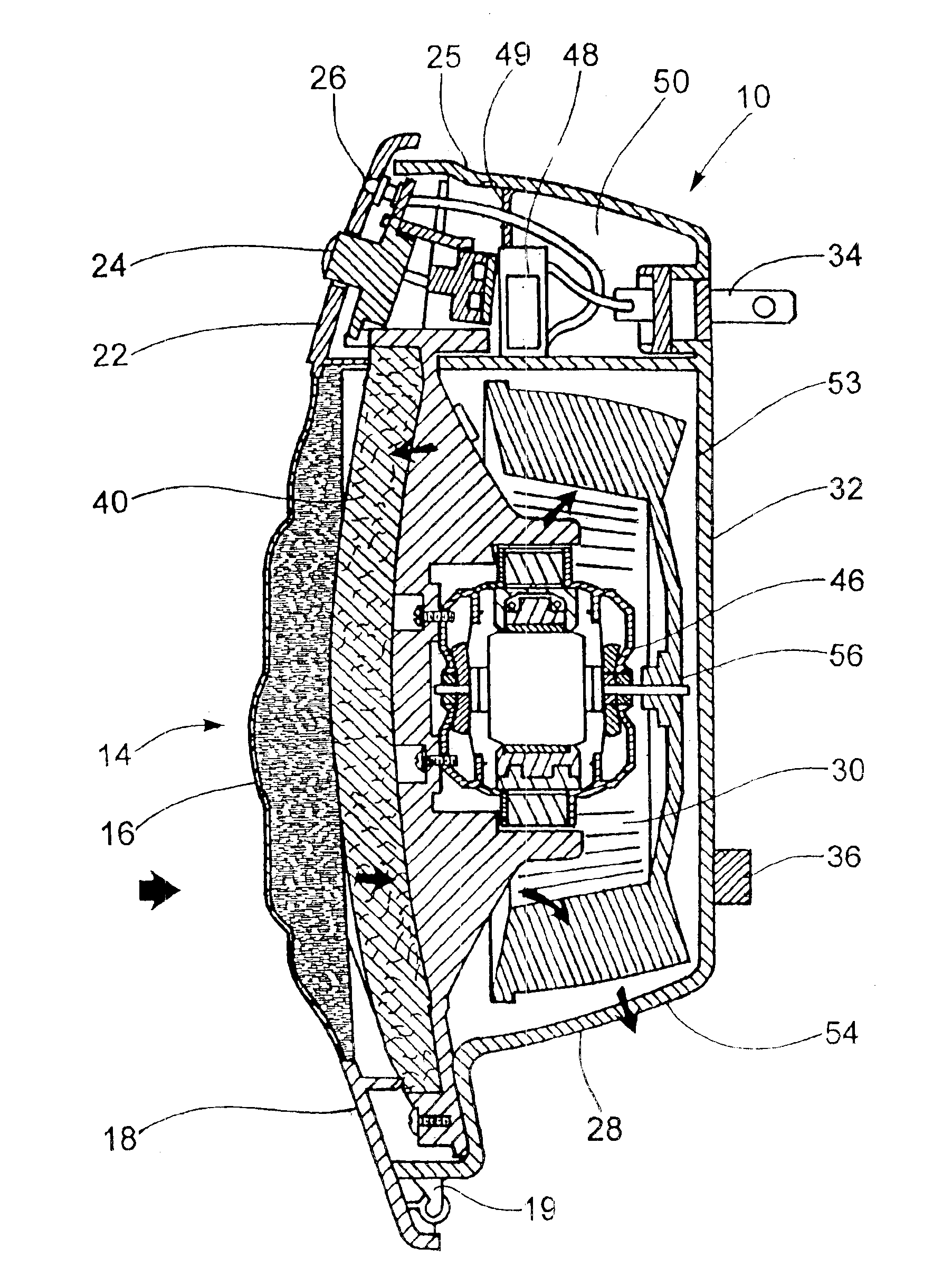
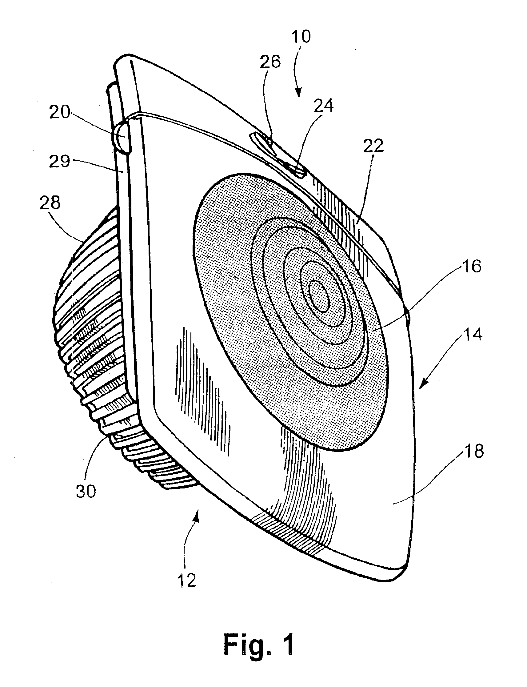
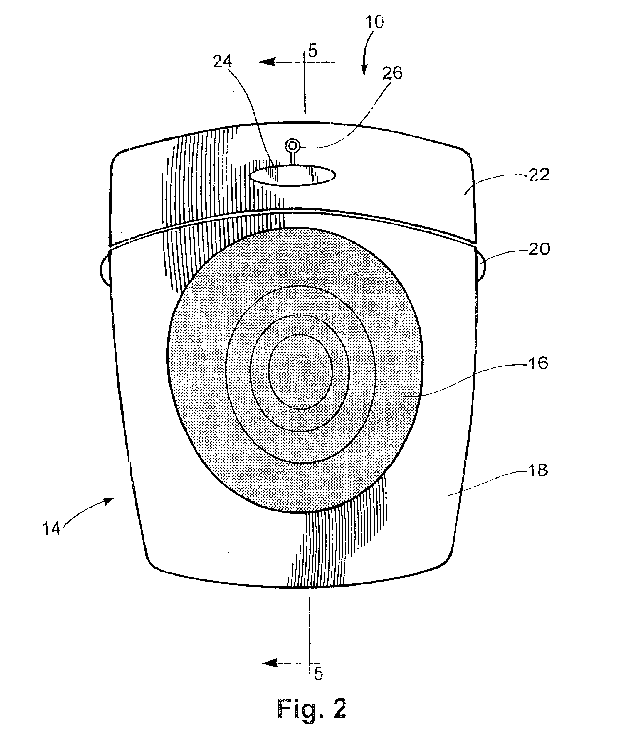
filtration device is provided for intake of atmospheric air, assistance in removal of contaminants from the atmospheric air, expulsion of filtered air and configured for operational association with a generally vertically oriented surface. The device includes a housing defining an air flow path therethrough having a front surface, at least one side surface and a rear surface; at least one air inlet formed in the front surface of the housing; and at least one air outlet formed in the housing intermediate the front surface and the rear surface, for cooperation of the air outlet with a generally vertical surface to which the air filtration device is associated for enhanced dispersion of filtered air expelled through the air outlet. A filter is mounted to the housing in the air flow path and an
impeller is provided for moving air through the housing along the air flow path from the at least one air inlet to the at least one air outlet, with the
impeller being mounted to the housing.
The air filtration device may further include a bumper member attached to the rear surface of the housing for
abutment with a generally vertical surface to which the air filtration device is associated for orientation of the device with the vertical surface. The bumper member may also be formed from resilient material for enhanced
noise reduction when the air filtration device is in operation. The filter can be formed as a generally planar member selectively removable from the housing and can include a notch formed therein for directing
insertion of the filter in a correct orientation with respect to the air flow path. The housing may include a locating surface formed thereon and corresponding with the notch in the filter to orient the filter in the housing. The housing may also include an icon formed thereon at a position corresponding with the notch in the filter when the filter is inserted in the housing for enhanced visual indication of proper filter orientation.
Accordingly, an air filtration device is provided for intake of atmospheric air, assistance in removal of contaminants from the atmospheric air, expulsion of filtered air and configured for operational association with a generally vertically oriented surface, and includes a housing for abutting attachment to an electrical outlet, the housing defining an air flow path therethrough and having a front surface, at least one side surface and a rear surface; at least one air inlet formed in the housing; at least one air outlet formed in the housing intermediate the front surface and the rear surface; a filter mounted to the housing in the air flow path; an electrically driven
impeller for moving air through the housing along the air flow path from the at least one air inlet to the at least one air outlet, with the impeller being mounted to the housing; and a pair of electric prongs extending outwardly from the rear surface for operational engagement with an electrical wall outlet for supplying
electric power to the impeller. The pair of electrical prongs can be configured with each prong in the pair having substantially the same dimensions, so that said air filtration device may be connected to an electrical outlet without regard to the dimensional differences between the socket openings. A bumper member is attached to the rear surface of the housing for
abutment with a generally vertical surface to which the bumper member may abut for orienting the device with the vertical surface. The bumper may be formed from resilient material for damping vibrations received from the housing to provide enhanced
noise reduction when the air filtration device is in operation.
The air filtration device includes an air inlet that is formed on the front surface of the housing and the air flow path is defined from the air inlet on the front surface through the filter, through the impeller and outwardly through the air outlet. The filter may be formed as a generally planar member selectively removable from the housing and includes a notch formed therein for directing
insertion of the filter in a correct orientation with respect to the air flow path. The housing may include a locating surface formed thereon and corresponding with the notch in the filter to orient the filter in the housing. The housing may include an icon formed at a position corresponding with the notch in the filter when the filter is inserted in the housing for enhanced visual indication of proper filter orientation.
It should also be understood that the above-described features may be combined under a single, full-featured unit. In that regard, an air filtration device for intake of atmospheric air, removal of contaminants from the atmospheric air, expulsion of filtered air and configured for operational association with a generally vertically oriented surface, includes a housing for abutting attachment to an electrical outlet, the housing defining an air flow path therethrough and having a front surface, a curved side surface and a rear surface; at least one air inlet formed in the front surface of the housing; and a series of vents formed in the side surface intermediate the front surface and the rear surface, for cooperation of the vents with a generally vertical surface to which the air filtration device is associated for enhanced dispersion of filtered air expelled through the vents. A filter is mounted to the housing intermediate the at least one air inlet and the at least one air outlet, with the filter being formed as a generally planar member selectively removable from the housing and including a notch formed therein for directing
insertion of the filter in a correct orientation with respect to the air flow path. The housing may include a locating surface formed thereon and corresponding with the notch in the filter to orient the filter in the housing. An electrically driven impeller is provided for moving air through the housing along the air flow path from the at least one air inlet to the vents, with the impeller being mounted to the housing. A pair of electric prongs extends outwardly from the rear surface for operational engagement with an electrical wall outlet for supplying
electric power to the impeller. The pair of electrical prongs can be configured with each prong in the pair having substantially the same dimensions, so that the air filtration device may be connected to an electrical outlet without regard to the dimensional differences between the socket openings. A bumper member is attached to the rear surface of the housing for abutment with a generally vertical surface to which the bumper member may abut for orienting the device with the vertical surface. The bumper member may be formed from resilient material for damping vibrations received from the housing for enhanced
noise reduction when the air filtration device is in operation.
By the above, the present invention provides an air filtration device that will plug directly into an outlet and utilize the wall behind the device for dispersion of filtered air, while directing air intake from a central source. The present invention also provides a handy visual indication of when the filter is placed in proper orientation with respect to air flow. Further, the device provides reduced noise by damping vibrations transmitted from the housing to the wall against which the device is mounted.


