Paste-bond clevis joint

a clevis joint and paste bond technology, applied in the field of components assembly, can solve the problems of increasing the weight and cost of the joint, the joint cannot be easily reassembled, and the use of fasteners adds weight and cost, so as to reduce the complexity and cost of fabrication, and reduce the effect of inter-laminar tension

Inactive Publication Date: 2005-03-08
LOCKHEED MARTIN CORP
View PDF13 Cites 37 Cited by
  • Summary
  • Abstract
  • Description
  • Claims
  • Application Information

AI Technical Summary

Benefits of technology

A woven preform transfers out-of-plane loading through directed fibers to minimize inter-laminar tension. The preform is cured in position on the skin, the web being inserted during final assembly into a clevis formed by the preform. Composite substructure components can be fabricated having flat, bladed webs, which reduces complexity and cost of fabrication. The result is an efficient way to assemble composite parts without the use of fasteners or flanged sections.

Problems solved by technology

Typical methods known in the art for attaching a composite skin to a composite web include forming the web as an “I” or “C” shape, making them more complex and expensive to fabricate.
However, use of the fasteners adds weight and cost to the joints.
Also, these joints have difficulty withstanding out-of-plane loading.
While this reduces the tensions forces between the layers of the flanged section, the result is a heavy joint, reducing the weight savings realized when using composites.

Method used


Image

  • Paste-bond clevis joint
  • Paste-bond clevis joint

Examples


Embodiment Construction

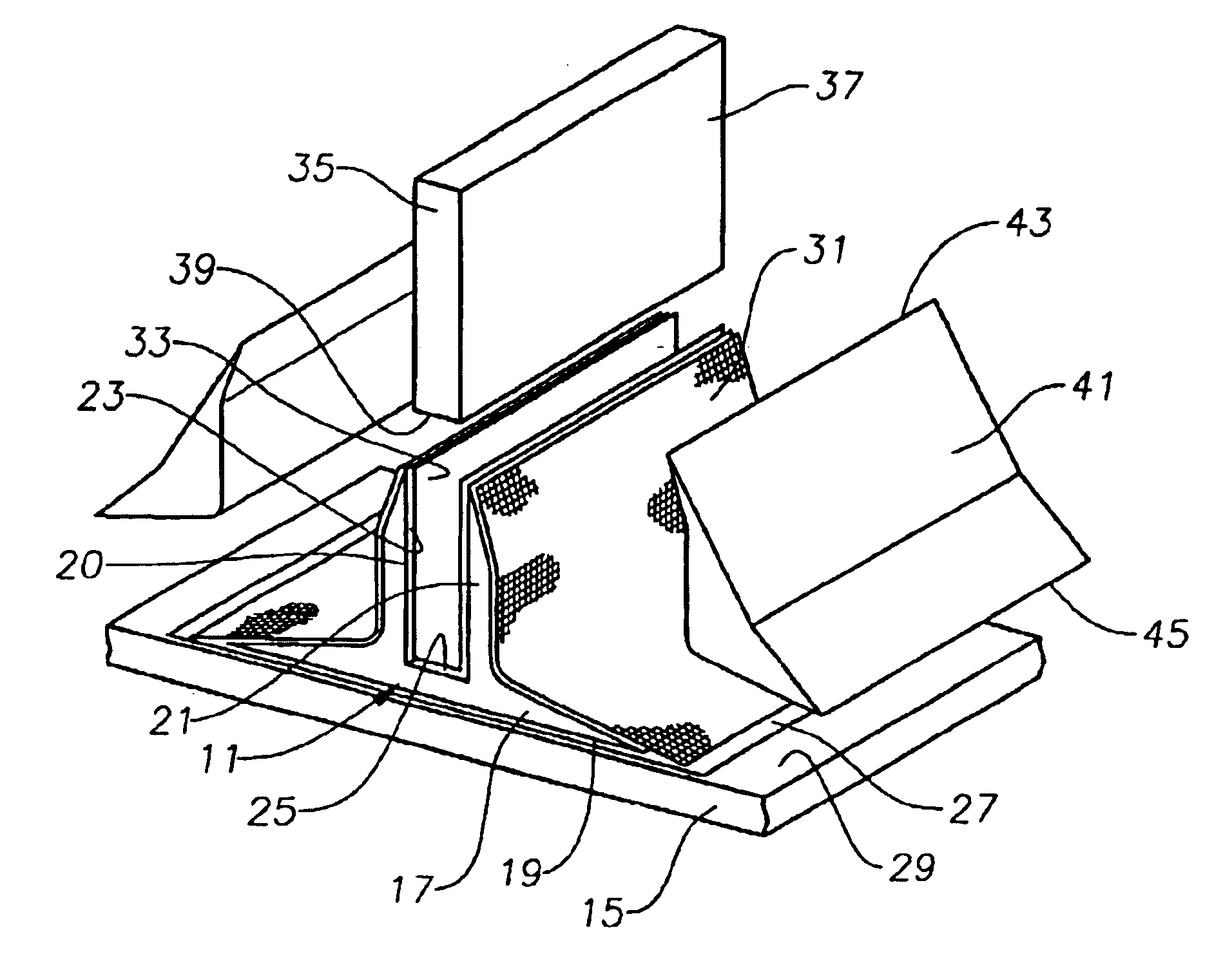
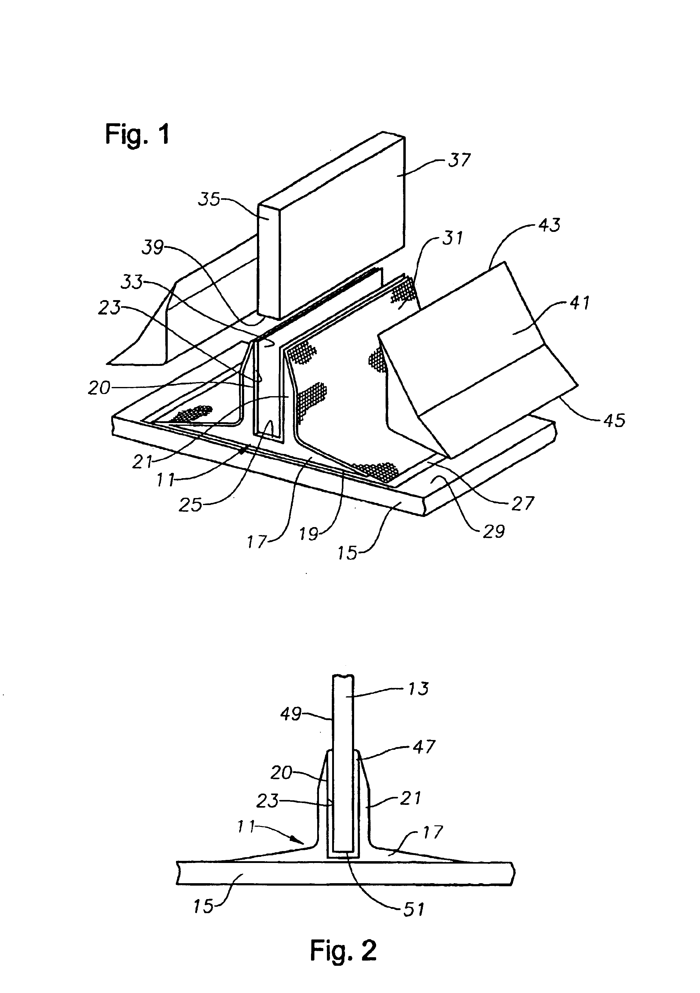
FIGS. 1 and 2 show a pi-shaped, 3-D, woven preform 11 used to connect two composite parts 13, 15, which may be, for example, a frame member 13 and a skin 15, or other member. Preform 11, frame 13, and skin 15 are infused with a resin, for example, 977-3, available from Cytec Industries, Inc. of West Paterson, N.J. Preform 11 is not cured prior to assembly. Frame 13 is cured prior to assembly, and skin 15 may be cured prior to preform 11 being adhered to skin 15. Alternatively, skin 15 and preform 11 may be co-cured as an assembly. Preform 11 may be woven from materials such as carbon fibers, Kevlar fibers, glass fibers, or other materials, or may be a combination of material types.

As shown in the figures, preform 11 has a base 17 on its lower portion that has a continuous, flat lower surface 19. A pair of spaced-apart planar legs 21 extend vertically upward from base 17, forming a clevis 20, or slot. Each leg 21 is at a position that is offset from, but near to, the center of base 1...


PUM

PropertyMeasurementUnit
tensile strengthaaaaaaaaaa
tensile strengthsaaaaaaaaaa

Abstract

A method is provided for using a three-dimensional, Pi-shaped, woven preform to assemble first and second composite components. The preform is infused with resin, and at least one surface of the preform is adhered to at least one surface of the first component using a film adhesive. The preform is cured while an oversized tool coated with non-stick material is located within a clevis formed by two legs of the preform. A removable peel ply is located between the tool and the clevis, and semi-rigid over-presses are used during curing. After curing, the tool, over-presses, and peel ply are removed, and adhesive is injected into the clevis. The second component is inserted into the clevis, the adhesive adhering to an inner surface of the clevis and to at least one surface of the second component for retaining the second component within the clevis, the second component having a smaller width than the tool.

Description

BACKGROUND OF THE INVENTION1. Field of the InventionThis invention generally relates to assembly of components using woven preforms and particularly relates to assembly using a paste adhesive within a clevis of a cured preform.2. Description of the Prior ArtTypical methods known in the art for attaching a composite skin to a composite web include forming the web as an “I” or “C” shape, making them more complex and expensive to fabricate. The flanged sections are fastened to adjacent sections using methods similar to those used with metal components, for example, by using fasteners. However, use of the fasteners adds weight and cost to the joints.Also, these joints have difficulty withstanding out-of-plane loading. Typical remedies for this are thick laminate stack-ups using many layers of composite fabric and having large flange radii. While this reduces the tensions forces between the layers of the flanged section, the result is a heavy joint, reducing the weight savings realized w...

Claims


Application Information

Patent Timeline
Patent Type & Authority Patents(United States)
IPC IPC(8): B29C65/00B29C70/04B29C70/10B29C70/30B29C70/22B64C1/00
CPCB29C66/43441B29C66/721B29C70/222B64C1/06B29C70/30B29C66/81455B64C2001/0072Y02T50/433B29K2995/0089B29C66/7315B29C65/4835B29C65/486B29C65/02B29C65/4865B29C66/1122B29C66/12441Y02T50/40
Inventor BERSUCH, LARRY R.HEAP, DAN V.BENSON, ROSS A.
Owner LOCKHEED MARTIN CORP
Why Eureka
Try Eureka