
Weight set for an electronic balance

a technology of electronic balance and weight set, which is applied in the direction of weighing apparatus, measuring devices, instruments, etc., can solve the problems of difficult access to individual lifting devices, complex arrangement, and high mechanical requirements, and achieve the effect of small space and easy exchang

Inactive Publication Date: 2005-03-08
METTLER TOLEDO GMBH
View PDF5 Cites 10 Cited by
  • Summary
  • Abstract
  • Description
  • Claims
  • Application Information

AI Technical Summary

Benefits of technology

It is therefore the objective of the invention to provide a weight set for a balance with the distinguishing traits that the weight set takes up a small amount of space, particularly in the horizontal dimensions, that it has a modular configuration, and that its lifter elements can be easily exchanged if they require servicing.
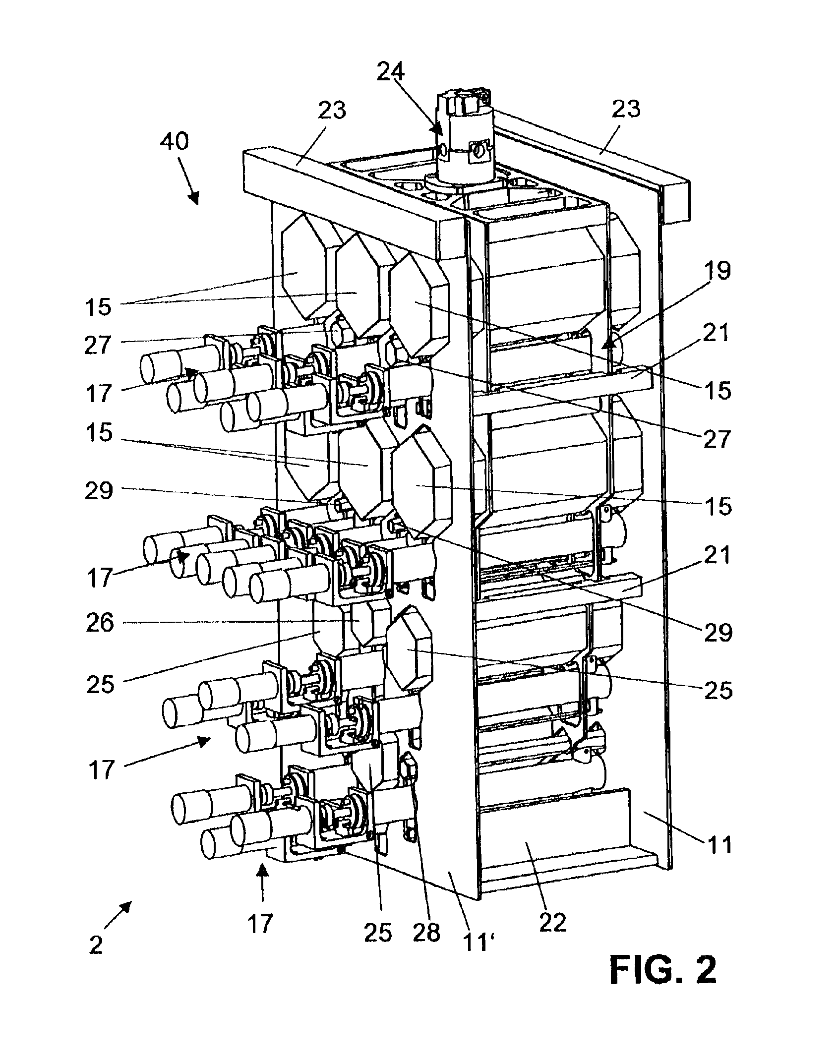
The invention offers the advantage that the individual lifter units provided for each weight allow the weights to be rapidly set on as well as lifted up from the balance pan. Due to the parallel arrangement of the lifter units and of the weights, the functions of putting the weights on the weight receiver device and subsequently taking them off again are realized with a low level of mechanical complexity. Servicing is made easy by the good accessibility and the exchangeability of the individual lifter units. Furthermore, the inventive concept provides for a compact arrangement of the weights in the weight set, with a compact width so that eccentric loading errors are to a large extent avoided.
In a preferred embodiment, the weight-receiving device is suspended from the device that supports the weighing pan and introduces the load, and the center of gravity of the weight-receiving device lies on a vertical line through the center of gravity of the weighing pan. In particular, the connection between the weight-receiving device and the pan-supporting device includes a coupling that largely avoids the introduction of a torque associated with putting weights on the weight-receiving device.
It is particularly advantageous if the arrangement of the weights in the weight set is mirror-symmetric relative to a plane that runs perpendicular to the carrier plates. The weight values are structured in binary multiples and submultiples of the base unit of 1 kg (i.e., 1 kg multiplied by any integer power of 2). This allows measurements of test weights in a continuous range between a maximum and minimum rated load for which the balance is designed.

Problems solved by technology

Devices of the present state of the art suffer from the drawback that there is either only one drive source provided to lower and lift the individual weights of the respective weight set on and off the balance pan, which makes the process very time-consuming, or if there are individual drive sources provided, the arrangement is complex and involves exacting mechanical requirements.
Also, the mechanism for lowering and lifting the ring-shaped, concentrically arranged internal compensation weights on and off the weighing pan is constructed in a complicated way, as the individual lifter devices have to be engaged in each other in order to reach the compensation weight that is to be moved.
Furthermore, difficulties have be expected in getting access to the individual lifting devices in case they require servicing.

Method used


Image

  • Weight set for an electronic balance
  • Weight set for an electronic balance
  • Weight set for an electronic balance

Examples


Embodiment Construction

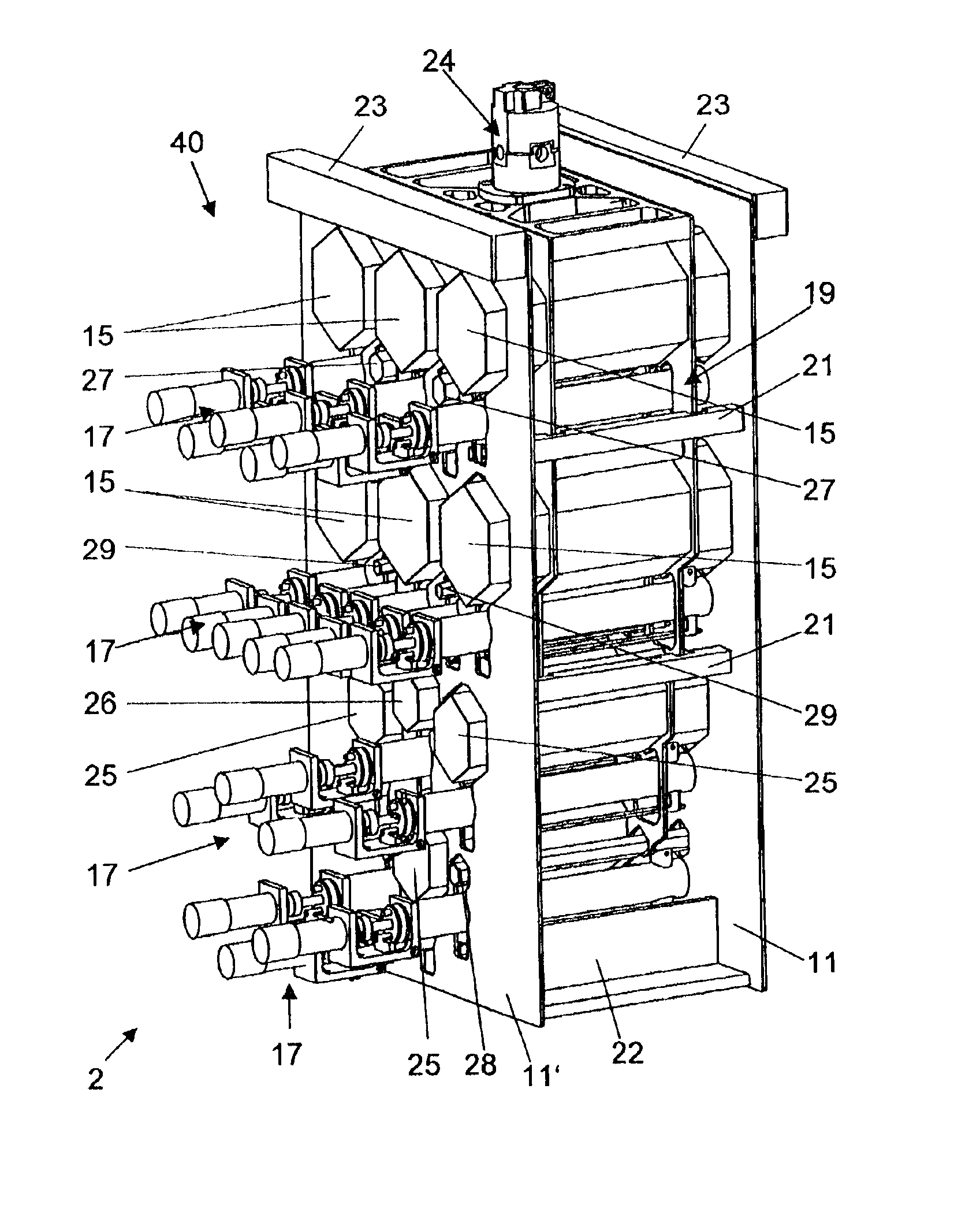
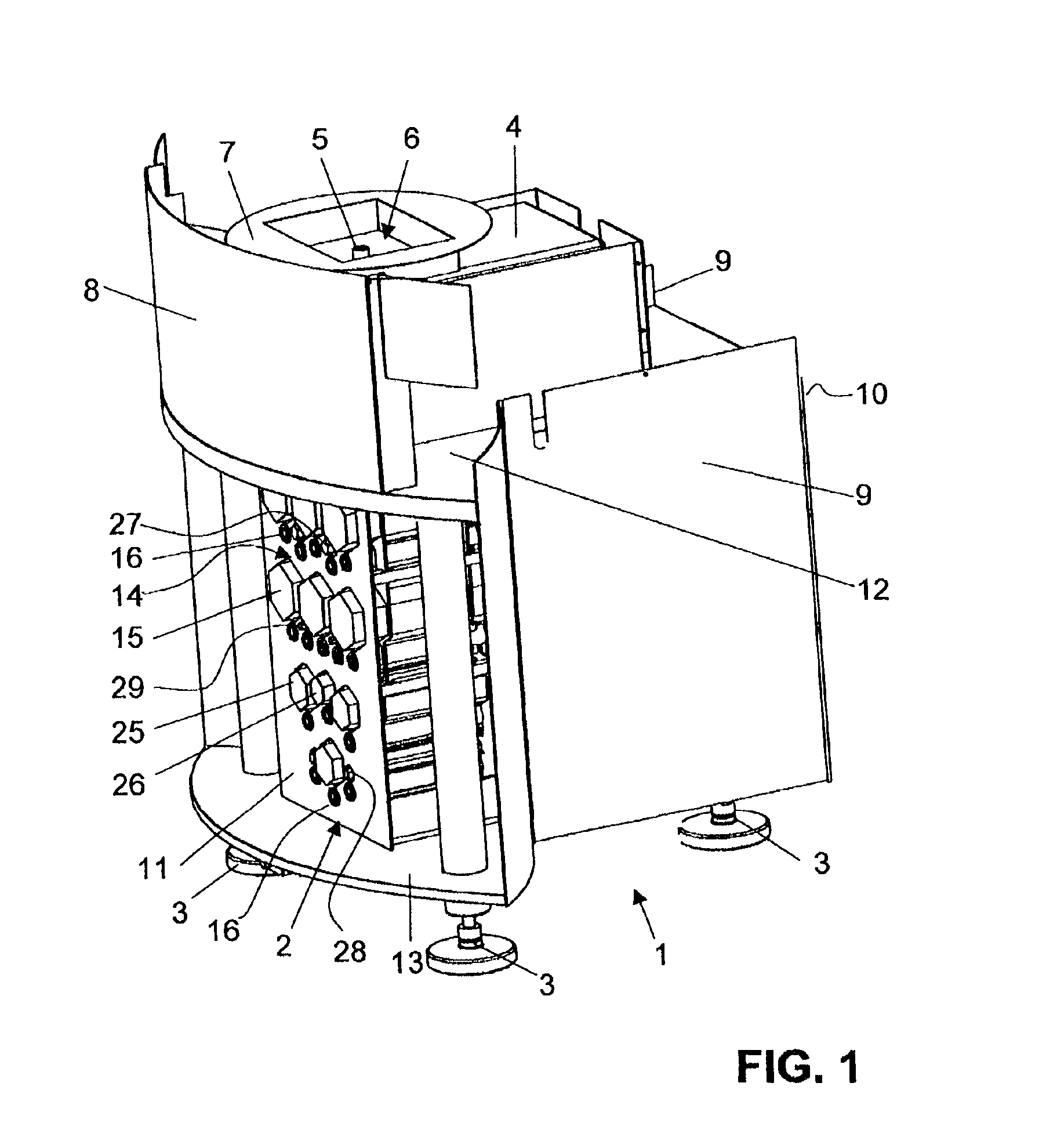
FIG. 1 gives a perspective view of a part of a comparator balance for high load values. The part illustrated in the drawing includes primarily a housing 1 in which the weighing device is accommodated. The only part of the weighing device that can be seen in the drawing is a weight set 2 arranged in the lower part of the housing 1. The housing 1 itself stands on three feet 3 which are height-adjustable so that the entire balance can be adjusted to a level position. A separate weighing cell housing 4 that contains the weighing cell (not visible in the drawing) can be seen in the upper part of the housing 1. A connector piece 5 that serves to introduce the load into the weighing cell and connects the weighing pan (not shown) to the weighing cell protrudes upwards through a passage opening of the weighing cell housing 4. The connector piece 5 is arranged at the center of a rectangular recess 6 of a shielding device 7 whose main purpose is to protect the access to the weighing cell as we...


PUM


Abstract

A weight set for an electronic balance has at least two different weights (15, 25, 26, 27, 28, 29) and a weight-receiving device (19) with receiving positions for each of the weights (15, 25, 26, 27, 28, 29). The weight set (2) has one lifter unit (17) per weight for the vertical movement of each individual weight (15, 25, 26, 27, 28, 29). The lifter units, which are equipped with a weight-seating device and reach through the weight-receiving device (19), are identical and are arranged parallel to each other in the weight set (2).

Description

BACKGROUND OF THE INVENTIONThe invention relates to a weight set for an electronic balance, in particular for a comparator balance. The balance has a weighing cell and a weighing pan as well as a mechanism that supports the weighing pan and transmits the load to the weighing cell. The weight set has at least two different weights and a weight-receiving device with at least two receiving positions, each of which is assigned to one of the weights.Comparator balances are used to perform accurate determinations of the mass or volume of weight pieces. Their application is predominantly in governmental institutes of metrology.In EP-A-1 098 177, an automatic calibration apparatus for test weights is disclosed which, in addition to a weighing unit and a processor unit, has three different weighing pans to hold standard weights, compensation weights and test weights. The test weights are weighed either on a single weighing pan with a weight-exchanging device that reaches through openings in ...

Claims


Application Information

Patent Timeline
Patent Type & Authority Patents(United States)
IPC IPC(8): G01G21/26G01G21/00
CPCG01G21/26
Inventor WEBER, RENE
Owner METTLER TOLEDO GMBH
Learn More