Piezoelectric resonator device having detuning layer sequence

a resonator device and layer sequence technology, applied in relays, generators/motors, impedence networks, etc., can solve the problems of difficult to meet, change of the thickness of the first electrode, and steps for fine-adjusting the resonance frequency

Inactive Publication Date: 2005-03-08
AVAGO TECH INT SALES PTE LTD
View PDF12 Cites 105 Cited by
  • Summary
  • Abstract
  • Description
  • Claims
  • Application Information

AI Technical Summary

Benefits of technology

It is the object of the present invention to provide a piezoelectric resonator device and a filter, the resonance frequency of which can be trimmed over a great frequency range without detuning leaving a tolerance range.

Problems solved by technology

These requirements are, however, difficult to fulfill in manufacturing the resonators described above so that further steps for fine-adjusting the resonance frequency must be taken.
The change of the thickness of the first electrodes 22, 22′, however, has the disadvantage of an undesired change of the detuning of the first resonator 10.
All the other filters having a larger variation cannot be corrected.

Method used


Image

  • Piezoelectric resonator device having detuning layer sequence
  • Piezoelectric resonator device having detuning layer sequence
  • Piezoelectric resonator device having detuning layer sequence

Examples


Embodiment Construction

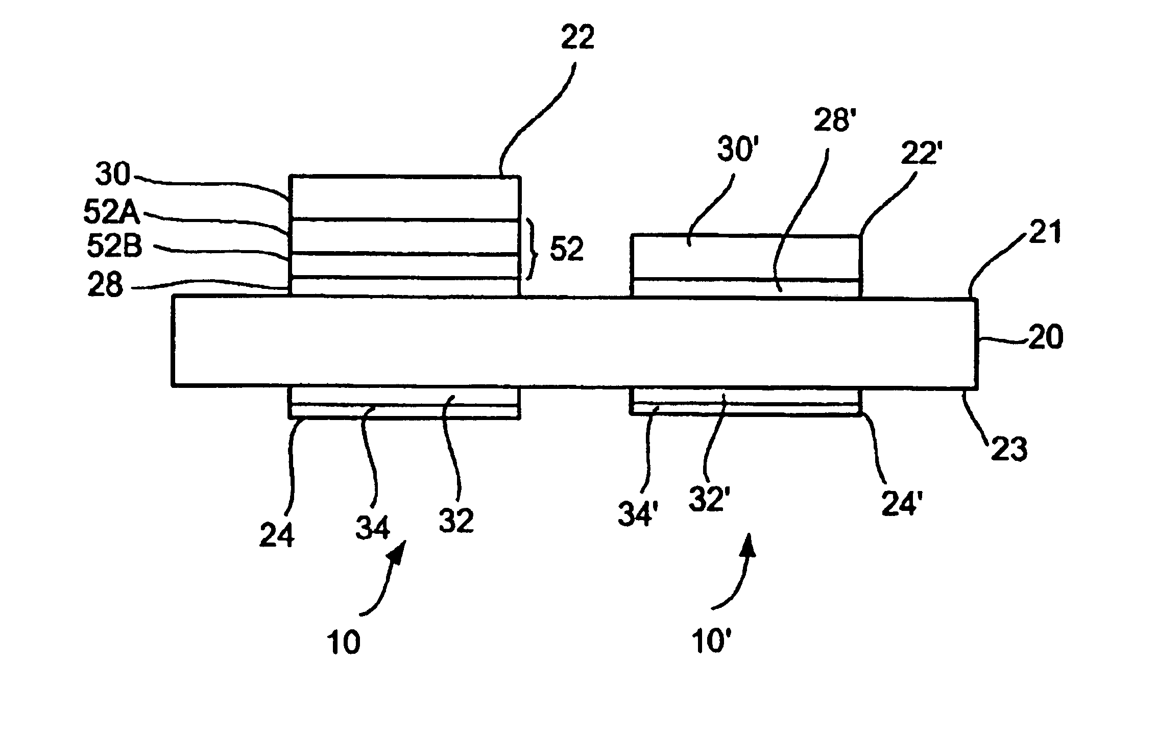
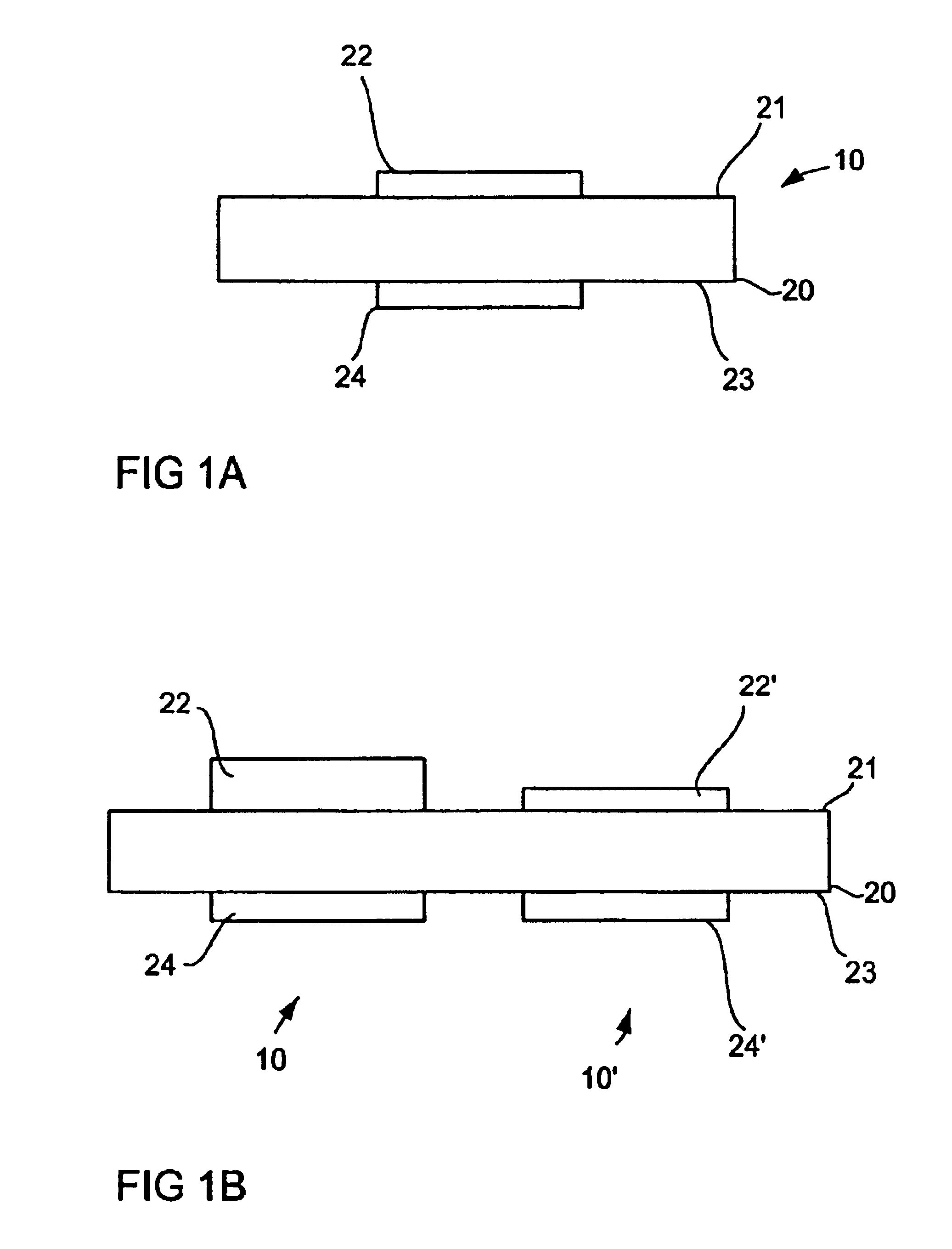
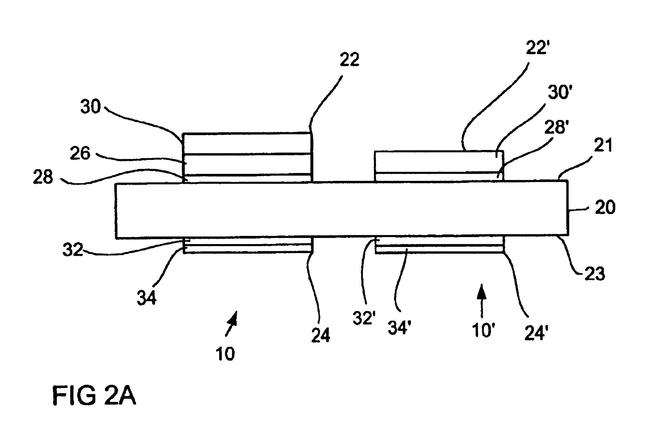
FIG. 3 shows a schematic sectional illustration of a preferred embodiment of a piezoelectric resonator device according to the present invention. Elements having already been described with reference to previous Figures have the same reference numerals and are not discussed again. FIG. 3 is a schematic illustration which is not to scale. The proportions of the layer thicknesses of the piezoelectric layer 20 and of the electrodes 22, 24 relative to one another and to the lateral extension of the layers can differ from the proportions illustrated. The lateral extension of the actual piezoelectric resonator 10 is only defined by the lateral extension of the superimposition region of the first electrode 22 and the second electrode 24. The first electrode 22 includes two layers 28 and 30 and the second electrode 24 includes two layers 32 and 34.

The piezoelectric resonator device in FIG. 3 differs from the detuned resonator 10 shown in FIG. 2A by the fact that instead of the individual de...


PUM


Abstract

A resonator device includes a piezoelectric resonator having a detuning layer sequence arranged on the piezoelectric resonator. The detuning layer sequence includes at least a first layer having a high acoustic impedance and a second layer having a low acoustic impedance.

Description

TECHNICAL FIELD OF THE INVENTIONThe present invention relates to piezoelectric resonator devices and, in particular, to a piezoelectric thin-layer resonator device having a detuning layer sequence comprising several layers having different acoustic impedances.DESCRIPTION OF THE RELATED ARTPiezoelectric resonators or bulk acoustic wave resonators (BAW resonators), respectively, are widely applied as filters in high frequency technology. In the widely used circuits of the ladder type or of the lattice or balanced type, several piezoelectric resonators are connected in series between an input and an output. In circuits of the ladder type, nodes between neighboring resonators are connected to ground via another BAW resonator (shunt resonator). In addition, further shunt resonators can be provided in parallel to the input and / or output of the filter. The one or the several shunt resonators have a resonance frequency which is typically lower by 2% to 3% than the resonance frequencies of t...

Claims


Application Information

Patent Timeline
Patent Type & Authority Patents(United States)
IPC IPC(8): H03H9/17H03H9/00H03H9/56H03H9/58H03H3/04H03H3/00
CPCH03H3/04H03H9/564H03H9/171H03H2003/0428H03H9/24
Inventor AIGNER, ROBERTLUEDER, ELBRECHTMARKSTEINER, STEPHANNESSLER, WINFRIED
Owner AVAGO TECH INT SALES PTE LTD
Why Eureka
Try Eureka