
Method and system for transmitting and displaying information on a wireless device using plastic electronics

a wireless device and plastic technology, applied in the field of large-area electronics and lighting systems, can solve the problems of complex wireless systems that exist today, increasing the overall system cost, and equipment less desirable for large-scale deploymen

Inactive Publication Date: 2005-03-08
KONINKLIJKE PHILIPS ELECTRONICS NV
View PDF15 Cites 1 Cited by
  • Summary
  • Abstract
  • Description
  • Claims
  • Application Information

AI Technical Summary

Benefits of technology

One aspect of the present invention provides a structure for displaying information on a portable wireless device that includes a power conversion unit and a central control unit operably connected to the pow

Problems solved by technology

Many of the wireless systems that exist today are complex systems and contain receiver terminals that operate on either Radio Frequency (RF) or infrared light.
This equipment typically requires a separate power supply, which increases the overall system cost.
This makes the equipment less desirable for large-scale deployment.

Method used


Image

  • Method and system for transmitting and displaying information on a wireless device using plastic electronics
  • Method and system for transmitting and displaying information on a wireless device using plastic electronics
  • Method and system for transmitting and displaying information on a wireless device using plastic electronics

Examples


Embodiment Construction

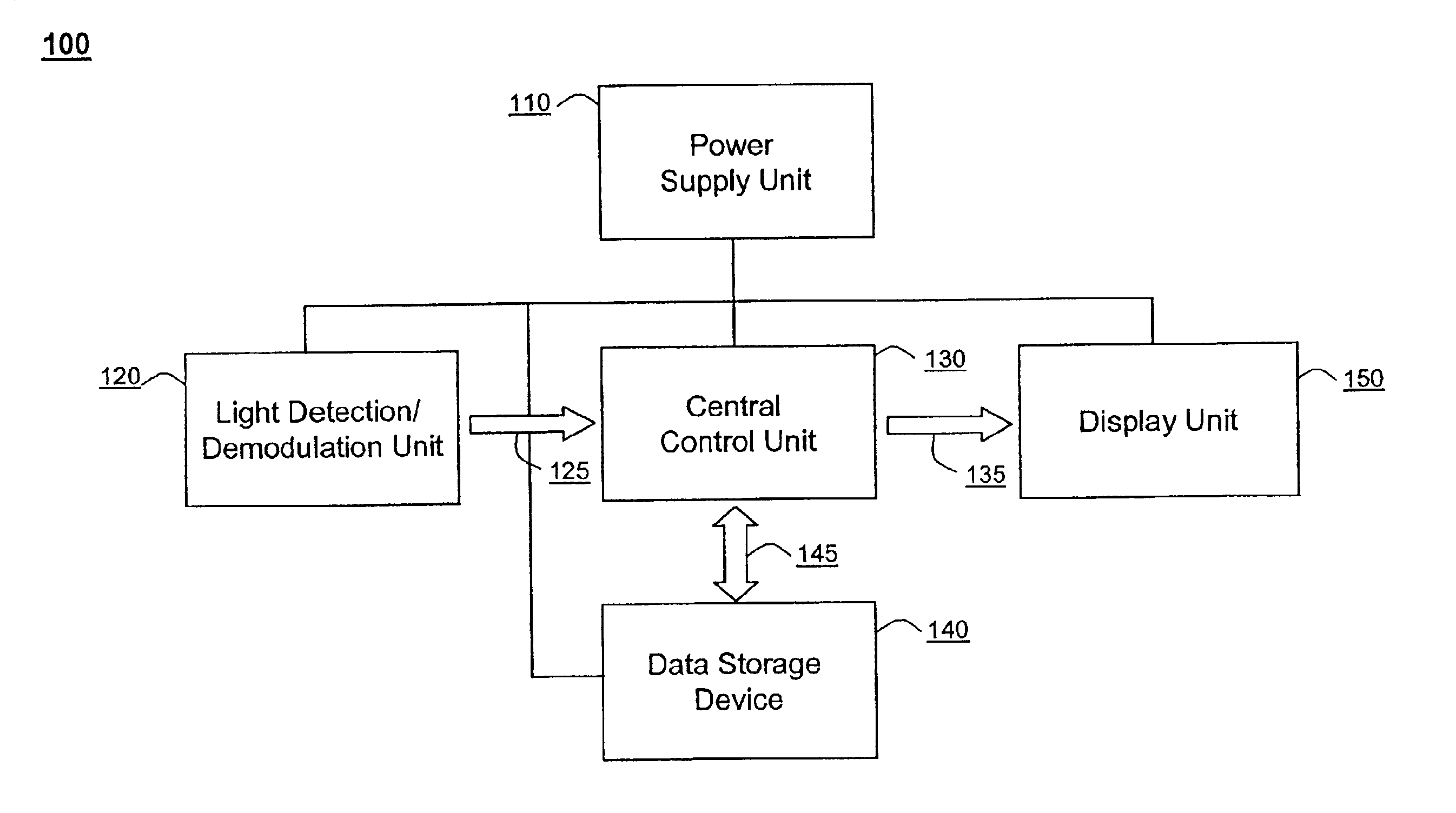
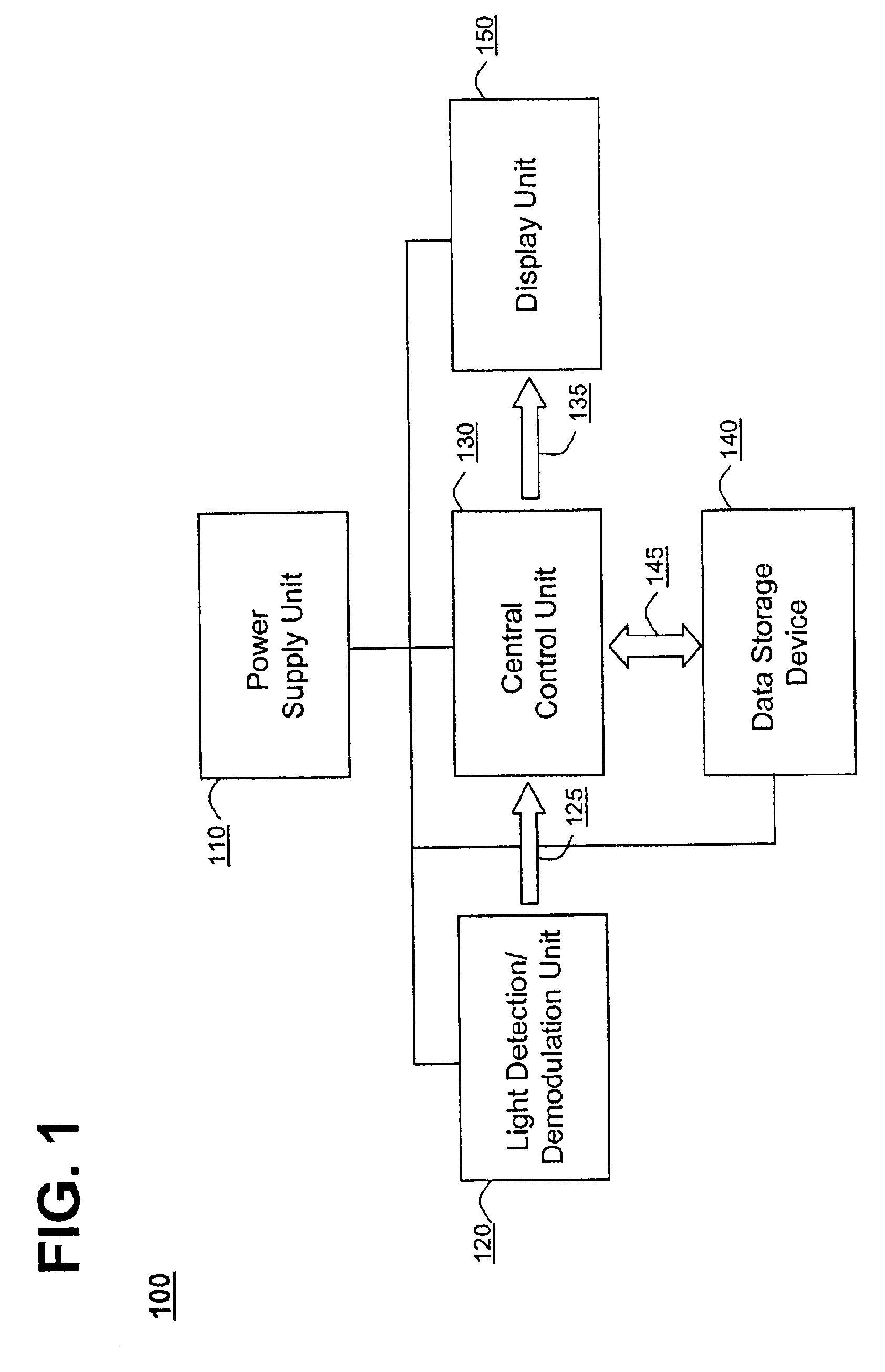
FIG. 1 shows one embodiment of a system for displaying information on a portable wireless device in accordance with the present invention at 100. The system may include a power conversion unit 110, a light detection / demodulation unit 120, a central control unit 130, a data storage device 140 and a display unit including associated driver circuitry 150. The devices 110, 120, 130, 140, 150 may be operably connected using wires, fiber optic connectors or any other suitable means known in the art.

The power conversion unit 110 may receive a light signal from any light source 105. The source 105 of light may be natural or artificial. For example, the light may be fluorescent light used in a large department store, morning sunlight or any other type of light known in the art.

In one embodiment, embedding data in the output of the florescent lamp and transmitting the data over the modulated light signal may be achieved by one of various modulation methods known in the art. This data may be a...


PUM


Abstract

The present invention provides a structure, method, computer program and a system for displaying information on a portable wireless device. This may be accomplished by receiving a light signal containing embedded data and converting the signal into electrical power. It may also be accomplished by demodulating the embedded data, retrieving information from the database in the storage device and displaying the information on a Light Emitting Polymer display screen.

Description

FIELD OF THE INVENTIONThis invention relates generally to using large area electronics and lighting systems. Specifically, it relates to a method of displaying information on a wireless device.BACKGROUND OF THE INVENTIONOften it is desirable to broadcast information to a large dispersed audience or in a high traffic area, for example a large department store. This is commonly accomplished using wireless communication systems. Many of the wireless systems that exist today are complex systems and contain receiver terminals that operate on either Radio Frequency (RF) or infrared light. This equipment typically requires a separate power supply, which increases the overall system cost. This makes the equipment less desirable for large-scale deployment.It would be desirable therefore to provide a system that overcomes the above disadvantages to provide a low cost device for displaying information using plastic electronics.SUMMARY OF THE INVENTIONOne aspect of the present invention provide...

Claims


Application Information

Patent Timeline
IPC IPC(8): G06K17/00H04B10/11H04B10/07H04B10/112H04B10/118H04B10/80
CPCG06K17/0022
Inventor VEILLETTE, BENOIT R.WANG, LING
Owner KONINKLIJKE PHILIPS ELECTRONICS NV
Learn More