Mechanism for supporting edge of motherboard

Inactive Publication Date: 2005-03-08
INVENTEC CORP
View PDF3 Cites 22 Cited by
  • Summary
  • Abstract
  • Description
  • Claims
  • Application Information

AI Technical Summary

Benefits of technology

A primary object of the present invention is to provide a support mechanism for holding up an edge of a rectangular motherboard. The support mechanism comprises a first hook at one end, a second hook at the other end both fastened at a substantially parallelepiped case of an electronic device, and an arcuate support section between the first and the second hooks. The support section fits onto an edge of the motherboard when the motherboard is secured to the c

Problems solved by technology

However, the prior motherboard fastening arrangement suffered from a disadvantage in spite of the easiness of assembly

Method used


Image

  • Mechanism for supporting edge of motherboard
  • Mechanism for supporting edge of motherboard
  • Mechanism for supporting edge of motherboard

Examples


Embodiment Construction

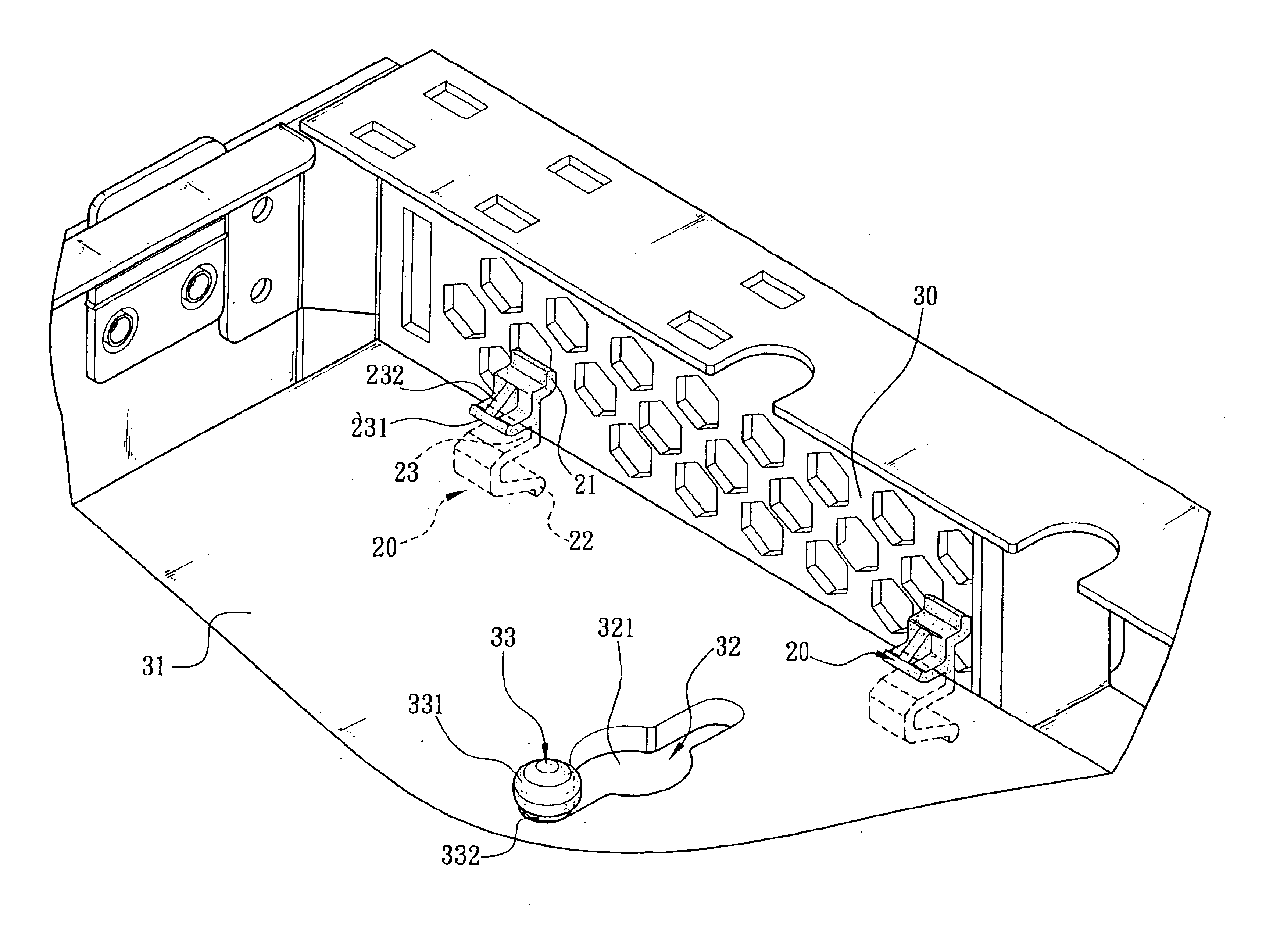
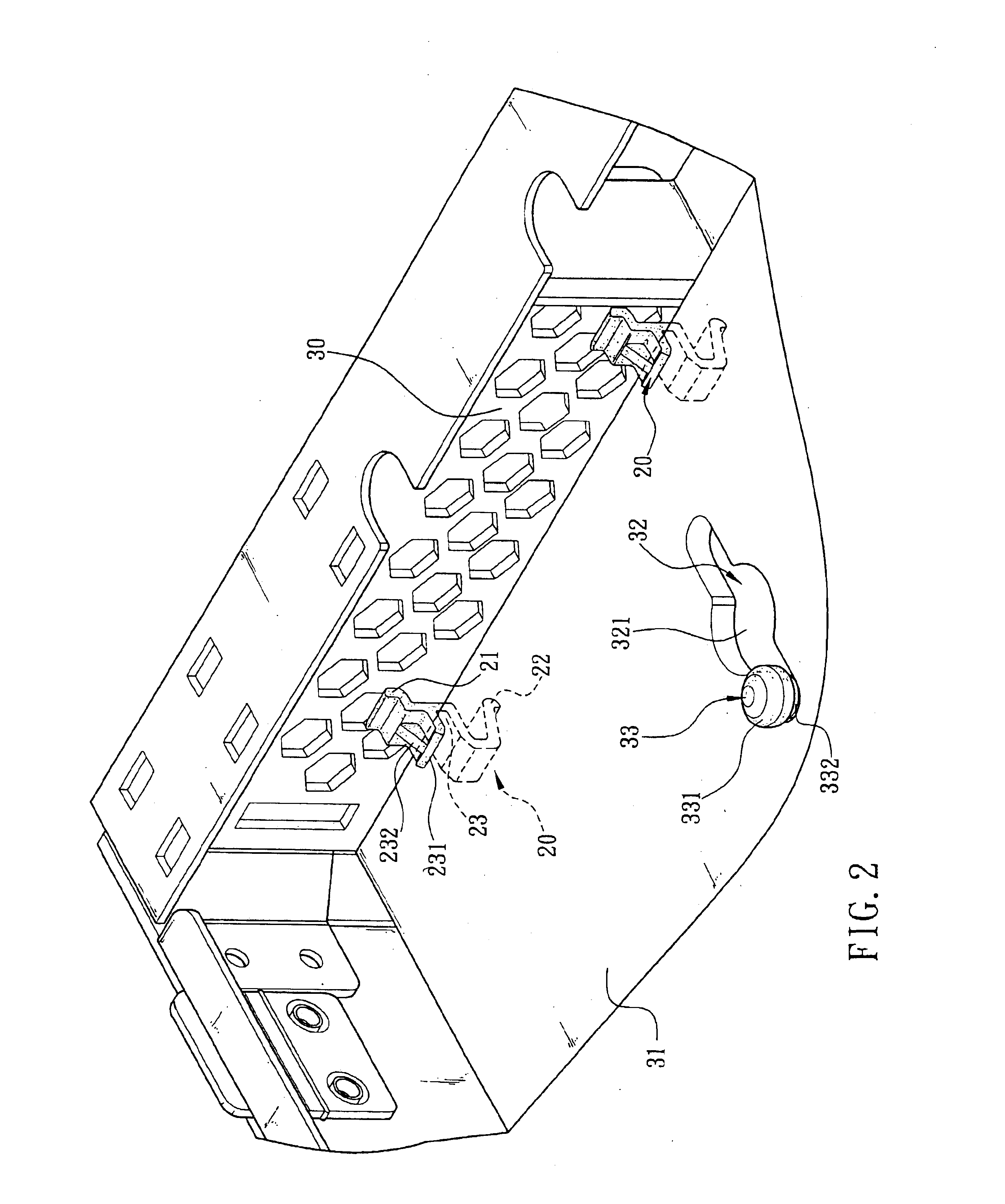
Referring to FIGS. 2 and 3, there is shown a support mechanism for holding up an edge of rectangular motherboard in accordance with the invention. The support mechanism 20 comprises a first hook 21 at an upper end and a second hook 22 at a lower end both fastened at a substantially parallelepiped case 30 of an electronic device (e.g., computer, industrial computer, cellular phone, etc.). The support mechanism 20 further comprises an arcuate support section 23 between the first and the second hooks 21 and 22. The support section 23 is adapted to fit onto an edge of a motherboard 31 when the motherboard 31 is secured to the case 30 of the electronic device by the support mechanism 20. As such, the edges of the motherboard 31 are fastened. Also, the edges of the motherboard 31 are free from vibration or even deformation when an external force is applied thereon in delivery. As an end, circuit devices of the motherboard 31 are free from damage due to the elimination of the vibration.

Ref...


PUM


Abstract

A support mechanism for holding up an edge of a rectangular motherboard. The mechanism includes a first hook at one end, a second hook at the other end both fastened at a substantially parallelepiped case of an electronic device, and an arcuate support section between the first and the second hooks. The support section fits onto an edge of the motherboard when the motherboard is secured to the case of the electronic device by the support mechanism, fastening the edge of the motherboard and preventing the edges of the motherboard from vibrating or deforming when an external force is applied thereon during delivery.

Description

FIELD OF THE INVENTIONThe present invention relates to support mechanisms and more particularly to a support mechanism for holding up edge of a motherboard of computer with improved characteristics.BACKGROUND OF THE INVENTIONA conventional arrangement of fastening motherboard of a typical electrical device (e.g., computer) is depicted in FIG. 1. As shown, the motherboard 10 comprises a plurality of elongated channels 11 each having a large, circular hole 111 in its center. A plurality of snapping members 12 corresponding the holes 111 are provided on a bottom of a substantially parallelepiped computer case. The snapping member 12 is a post-like element and comprises a round head 121, a neck 122 having a smaller diameter, and a base (not shown) coupled to the bottom of the case. In assembling the motherboard 10 in the computer case, first cling the hole 111 of the channel 11 of the motherboard 10 onto the neck 122 of the snapping member 12. Next, move the motherboard 10 toward one si...

Claims


Application Information

Patent Timeline
IPC IPC(8): H05K7/14
CPCH05K7/142
Inventor HSU, CHENG-CHUNG
Owner INVENTEC CORP
Why Eureka
Try Eureka