
LED intense headband light source for fingerprint analysis

a fingerprint analysis and headband technology, applied in the direction of lighting support devices, instruments, lighting and heating apparatus, etc., can solve the problems of limiting the free range of movement of users, cumbersome and heavy, and costing approximately $10,000

Inactive Publication Date: 2005-03-08
THE UNITED STATES AS REPRESENTED BY THE DEPARTMENT OF ENERGY +1
View PDF10 Cites 45 Cited by
  • Summary
  • Abstract
  • Description
  • Claims
  • Application Information

AI Technical Summary

Benefits of technology

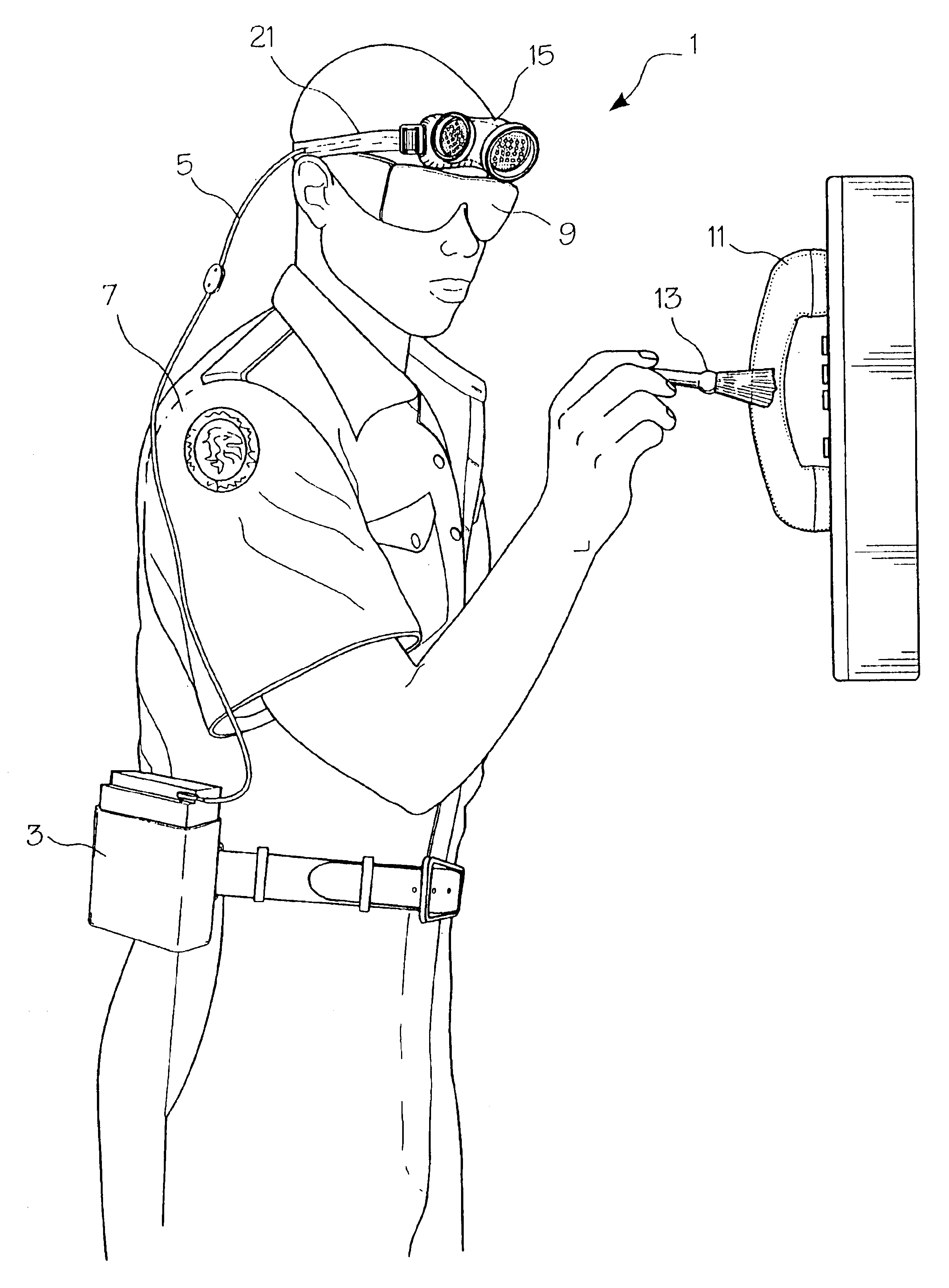
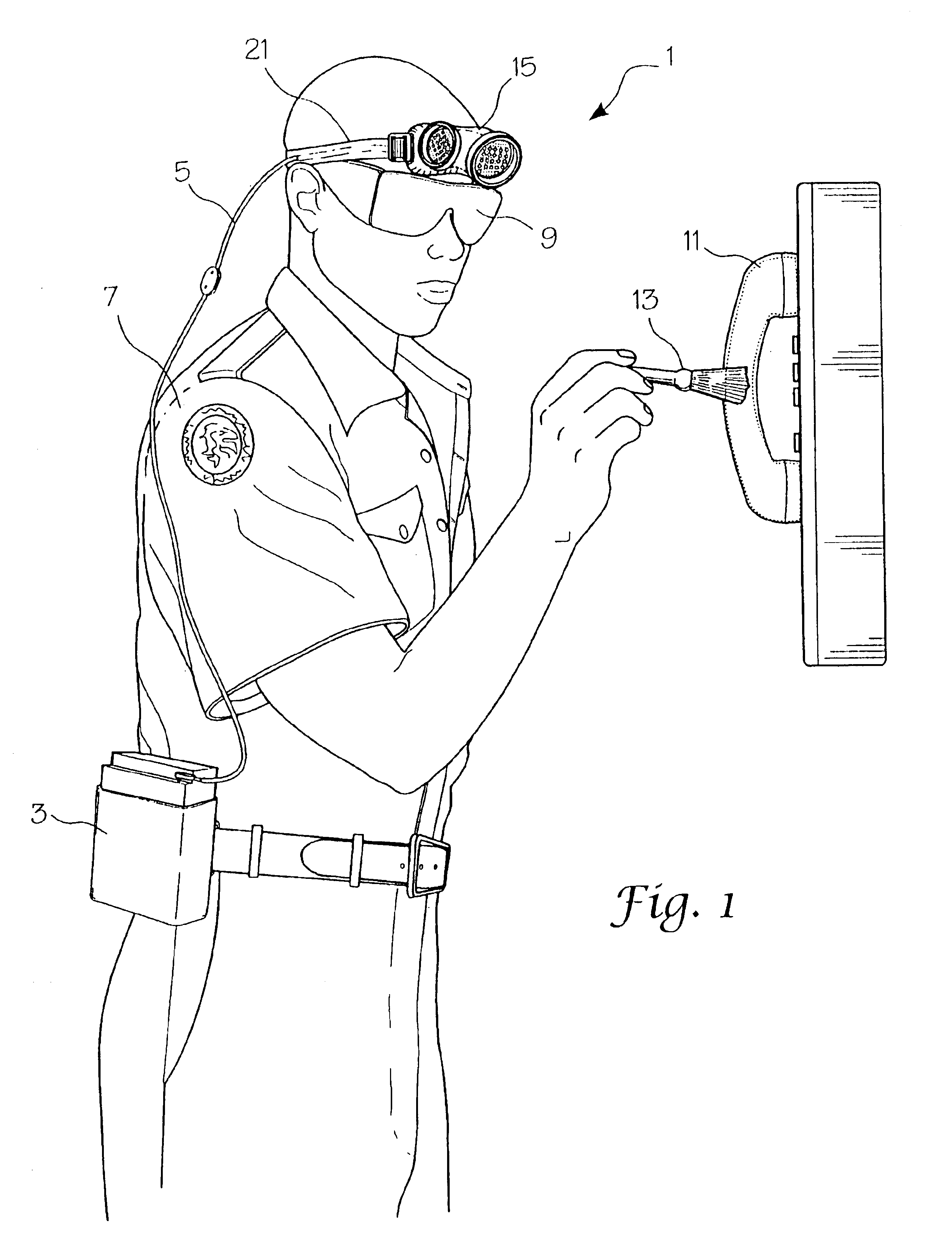
"The present invention provides a portable and high-intensity light source for on-site fingerprint detection and analysis. The device comprises an array of light emitting diodes powered by a power source, which emits wavelength-specific light of sufficient intensity to cause a dye to visibly fluoresce and produce a personal light source for on-site analysis of latent fingerprints, footprints, or other markings. The device is small and light enough for field use during on-site investigation and does not require hand holding. It allows freedom of movement during use and is sufficient in intensity to cause a dye to fluoresce and produce a signal that can be detected by the human eye."

Problems solved by technology

Though they produce the requisite high-intensity light, these sources present a number of problems.
They are very expensive, costing approximately $10,000.
They are cumbersome and heavy, weighing about 20 pounds, and moreover, they require high voltage electrical power in the order of about 115 V of 5 amps of current, most commonly provided by AC wall outlets.
As a result, they limit a user's free range of movement.
These and other aspects of the device, make it and other such devices difficult to use depending on their intended application.
Although satisfactory in some respects, there are significant disadvantages associated with this device.
As such, the device is not suitable for on-site latent fingerprint detection and analysis.
Thus, the device is not suitable for on-site analysis or investigation of latent fingerprints left by unknown parties.
It is not suitable for field analysis, especially for latent fingerprints of unknown parties.
It does not provide, however, for the collection of latent fingerprints left by unknown parties.

Method used


Image

  • LED intense headband light source for fingerprint analysis
  • LED intense headband light source for fingerprint analysis
  • LED intense headband light source for fingerprint analysis

Examples


embodiment 20

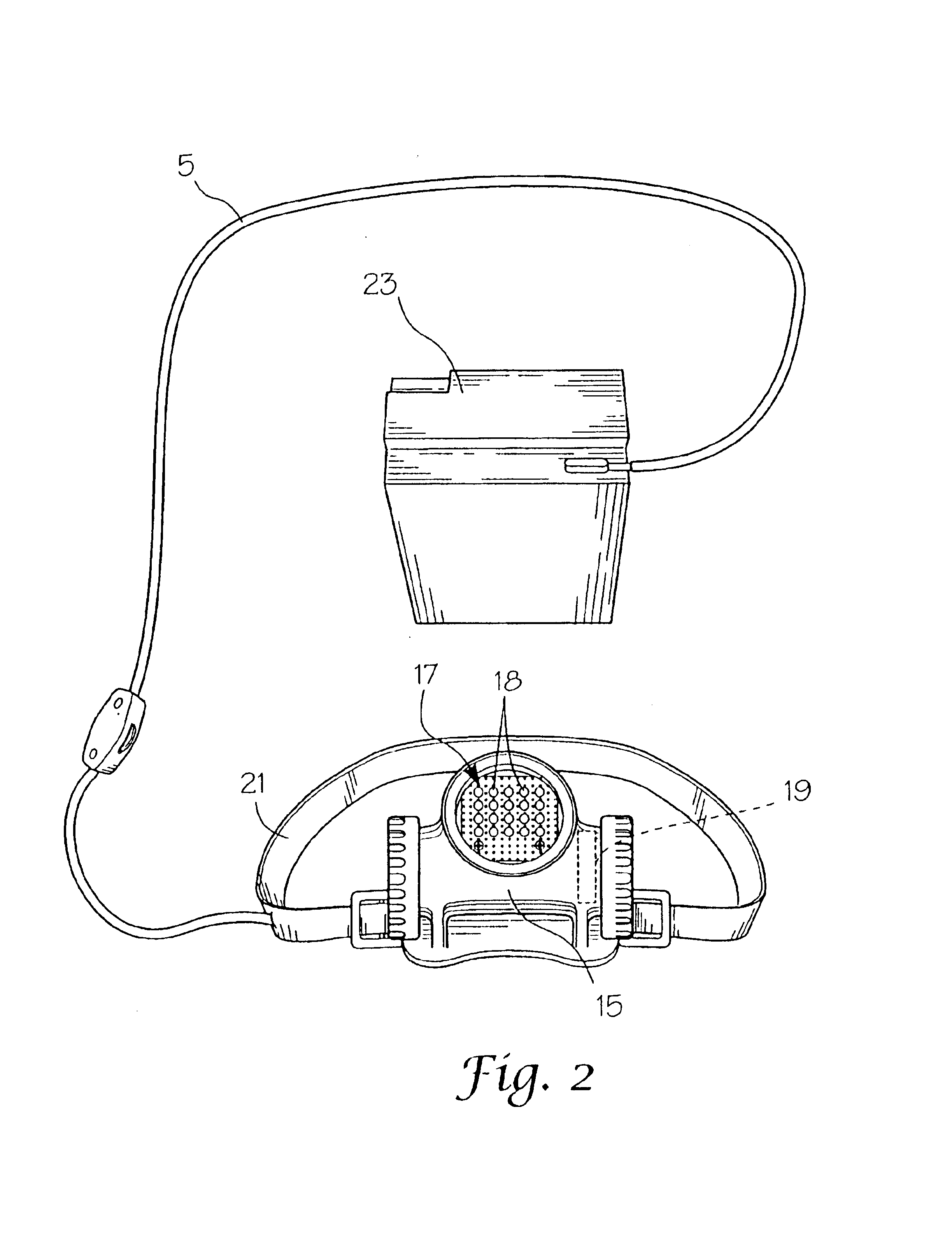
An array of LEDs increases the intensity of the light source. In a preferred embodiment 20 LEDs are used. In an alternate preferred embodiment for commercial use, the system has between about 40 and 60 LEDs. In another alternate preferred embodiment, it seems that the best compromise for light production to battery charge calls for an array of between about 60 to 80, 470 nm LEDs. It is noted however, that an array of LEDs numbering from about three to well over one-hundred may be used, preferably including arrays having from about 10 to about 100 LEDs.

The wavelength of the LED is chosen according to the dye used during the dusting of latent fingerprints. At least in several cases, the dye absorbs shorter wavelengths of light than that of the corresponding fluorescence. It should be noted that an array of LEDs which emit green wavelength light may be used.

In a preferred embodiment, and as seen in FIG. 1, the device of the present invention comprises a headset 1, a powersource belt po...

example 1

Using a 470 nanometer source of 6 LEDs, the spectra of white paper and rhodamine 6G dye on paper, illumination by these LEDs was recorded using a spectroradiometer obtainable from Analytical Systems Device, Incorporated. As seen, the LEDs emit light having a wavelength from between about 400 nm to about 550 nm. The LEDs radiated light onto white paper covered with rhodamine 6G dye. More specifically, the LED was shown onto a Spectralon target held at about one meter away from the light source. It scattered light in all directions (lambertian). The fiber optic of the spectroradiometer was directed to the illuminated portion of the Spectralon target. FIG. 5 plots the resulting reflective light radiance (W / m2-sr-nm) as measured by the above-mentioned spectroradiometer.

example 2

Using an array of six 430 nanometer emitting LED reflective illumination of white paper versus rhodamine 6G dye on the white paper was measured using a spectroradiometer obtainable from Analytical Systems Device, Incorporated. Reflective light radiating from the 430 nanometer LED's and then reflectively radiating off of white paper and the dye produced the three curves shown on FIG. 6. As seen, the LEDs emit light having a wavelength from between about 400 nm to about 550 nm. As also seen, the curve designated by squares show reflection of 430 nanometer illumination off of white paper not having dye attached thereto. The curve designated with plus signs illustrates reflection of 430 nanometer blue illumination and emmited fluorescence light produced by rhodamine 6G dye. The third curve designated by triangles is of the filtered reflected fluorescence from rhodamine 60 dye as viewed through an orange filtering lens. As seen in this third curve, light reflecting off of plain white pap...


PUM


Abstract

A portable, lightweight and high-intensity light source for detecting and analyzing fingerprints during field investigation. On-site field analysis requires long hours of mobile analysis. In one embodiment, the present invention comprises a plurality of light emitting diodes; a power source; and a personal attachment means; wherein the light emitting diodes are powered by the power source, and wherein the power source and the light emitting diodes are attached to the personal attachment means to produce a personal light source for on-site analysis of latent fingerprints. The present invention is available for other applications as well.

Description

BACKGROUND OF THE INVENTIONField of the InventionThe present invention relates to devices for detecting and analyzing fingerprints, and more particularly, the device of the present invention relates to a light source for on-site investigatory fingerprint detection and analysis.Fingerprint acquisition by law enforcement personnel in the field can be a slow process when timeliness in suspect apprehension is imperative. The current method of acquiring and identifying latent fingerprints is to “dust” an area where they are believed to have been recorded. An officer then carefully uses tape to lift the print for transport to a laboratory. In the laboratory the prints are compared with known prints on file or are sent to a central lab for further processing and identification. Before comparing it with other prints, however, the print first must be detected and the time required to cover crime scenes may be prolonged, especially for larger areas of investigation having many surfaces. There...

Claims


Application Information

Patent Timeline
Patent Type & Authority Patents(United States)
IPC IPC(8): G06K9/00G06V40/13
CPCG06K9/00013G06V40/13
Inventor VILLA-ALEMAN, ELIEL
Owner THE UNITED STATES AS REPRESENTED BY THE DEPARTMENT OF ENERGY
Learn More