Photographic fingerprint collection and imaging system

a fingerprint collection and imaging system technology, applied in the field of fingerprint collection system, can solve the problems of difficult observation and collection of latent fingerprints, difficult techniques that require expensive digital cameras, and high cost of digital cameras

Active Publication Date: 2012-09-11
AZIMUTH
View PDF20 Cites 14 Cited by
  • Summary
  • Abstract
  • Description
  • Claims
  • Application Information

AI Technical Summary

Benefits of technology

[0011]Using the present device, invisible fingerprints, visible prints and plastic prints can be captured without destroying the physical evidence. The device of the present invention controls the lighting, exposure, focus, field of view and depth of view (all of which are constants in accordance with the present invention), thereby maximizing the quality of the image while requiring little or no adjustment by the user. Specifically, lighting is controlled by the automated configuration or adjustment of lighting intensity (including the attenuation or ambient lighting), the light to shutter gating and duration, and the incidence angle of light (including oblique angle and backlighting).
[0014]Because the structure of the present invention is fixed in size, and provides a constant FOV, DOF, sensor size, and magnification, the structure is easy to use, the software on the associated computer can be simplified, errors are reduced, and image quality is increased. Furthermore, because the device of the present invention sets the lens to a fixed focal length, there is no need to capture a ruled scale in the image.
[0015]The device of the present invention is further designed for simplicity of operation, by having a single push button to capture the image, and a single multi-position switch to select illumination frequency (e.g., IR, white, UV). Furthermore, the form, fit, and function of the device include several advantages for its intended purpose, including the fact that it is small and light weight, and consumes only a small amount of power.

Problems solved by technology

The first challenge to collecting latent fingerprints is the ability of identifying them on objects.
Latent fingerprints are difficult to observe and collect, because typically only a tenth of a milligram of material is deposited on the surface.
However, these techniques can require expensive digital cameras because of specialized Charged Coupled Devices (CCD), lenses, and optical filters that are sensitive to the frequency of light used to illuminate the fingerprint.
However, this camera is very complicated to use, expensive and requires additional lighting sources.

Method used


Image

  • Photographic fingerprint collection and imaging system
  • Photographic fingerprint collection and imaging system
  • Photographic fingerprint collection and imaging system

Examples


Embodiment Construction

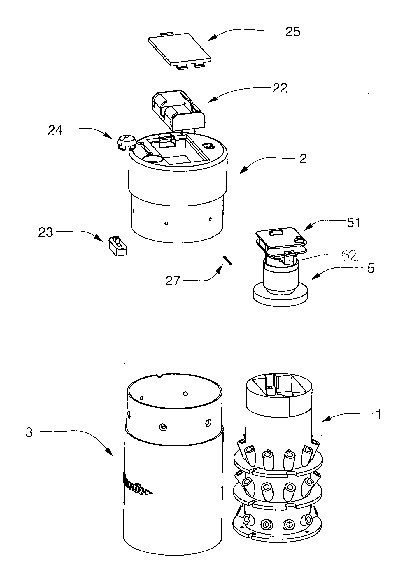
[0035]Lens System. The lens system of the present invention comprises a lens 5, a support bracket 52, and a circuit board 51. In an embodiment, the lens is a single element 16 mm lens coupled with a sensor having a resolution of between 1600 and 2000 pixels (or higher), having a form factor of ⅓″ CCD and a spectral response at wavelengths of 380-750 nm (for visible detection) and 365-405 nm (for UV fluorescence detection). The sensor further comprises a TWAIN interface to allow it to communicate with image processing software.

[0036]Furthermore, preferably coupled with the lens are illumination optics, including a thermo formable diffuser film, matt finish, with at least 60% transmissivity.

[0037]Image Sensors. There are two available sensor technologies solutions to image fingerprints given the present application: the CCD (Charge Coupled Device) and the CMOS (Complimentary Metal Oxide Semiconductor). Both technologies capture light from the lens, and convert it into electronic signa...


PUM


Abstract

The present invention regards a system comprised of a camera lens, a sensor, a light source and a structure for directly collecting (imaging) latent fingerprints from surfaces, either naturally or with a reagent to fluoresce, and suitable for use in military tactical environments. The present invention is intended to be used with a portable computer, having software capable of receiving, storing and processing images collected by the device of the present invention.

Description

BACKGROUND OF THE INVENTION[0001]The present invention regards a fingerprint collection system comprising a camera lens, a sensor, a light source and a cylindrical structure, for directly collecting (imaging) fingerprints from surfaces, either naturally or with a reagent to fluoresce, and is suitable for use in military tactical and practical investigative environments. The present invention is intended to be used with a portable computer, having software capable of receiving, storing and processing images collected by the device of the present invention.[0002]The first challenge to collecting latent fingerprints is the ability of identifying them on objects. Latent fingerprints are difficult to observe and collect, because typically only a tenth of a milligram of material is deposited on the surface. About 99% of a latent fingerprint is water, which soon evaporates to leave behind about a microgram of residue. About half of this residue is inorganic material, such as sodium chlorid...

Claims


Application Information

Patent Timeline
Patent Type & Authority Patents(United States)
IPC IPC(8): G06K9/00G06V40/13
CPCA61B5/0059A61B5/1172G06K9/00013G06V40/13
Inventor NEOH, KENNETH C.HURT, JOHN
Owner AZIMUTH
Why Eureka
Try Eureka