Flexographic Printing Plates and Methods

a printing plate and flexographic technology, applied in the field of flexographic printing plates and methods, can solve the problems of significantly more time for application and drying of ink, and achieve the effects of increasing the production speed of such plates, sufficient opacity, and improving quality

Inactive Publication Date: 2015-11-12
CHEMENCE
View PDF1 Cites 2 Cited by
  • Summary
  • Abstract
  • Description
  • Claims
  • Application Information

AI Technical Summary

Benefits of technology

[0008]The principal object of this invention is to enable making flexographic plates from sheet photopolymers by printing them without the need for pre-applying an inkjet-receptive coating. Another object of the invention is to improve the quality and increase the production speed of such plates using solvent-based inkjet inks which are of sufficient opacity that only one inkjet layer is needed, and exposure to UV can be performed without using a conventional exposure unit.SUMMARY OF THE INVENTION
[0009]The present invention enables relief images to be produced in currently-available sheet photopolymers by printing them with single non-overlapping print head passes using solvent-based inks without the need for an inkjet-receptive coating. A solvent ink that will adhere to the surface of the photopolymer slip film with no coating is used and, in embodiments, quick-dried to maximize image quality by heating the inked surface up to about 50° C. In embodiments, sheet photopolymer plates so produced can then be exposed to UV light in a modified printer that, in effect, transforms a batch process to a continuous one. These and other benefits will become clear in the following detailed description and attached drawings.

Problems solved by technology

This requires significantly more time for application and drying of the ink.

Method used


Image

  • Flexographic Printing Plates and Methods
  • Flexographic Printing Plates and Methods
  • Flexographic Printing Plates and Methods

Examples


first embodiment

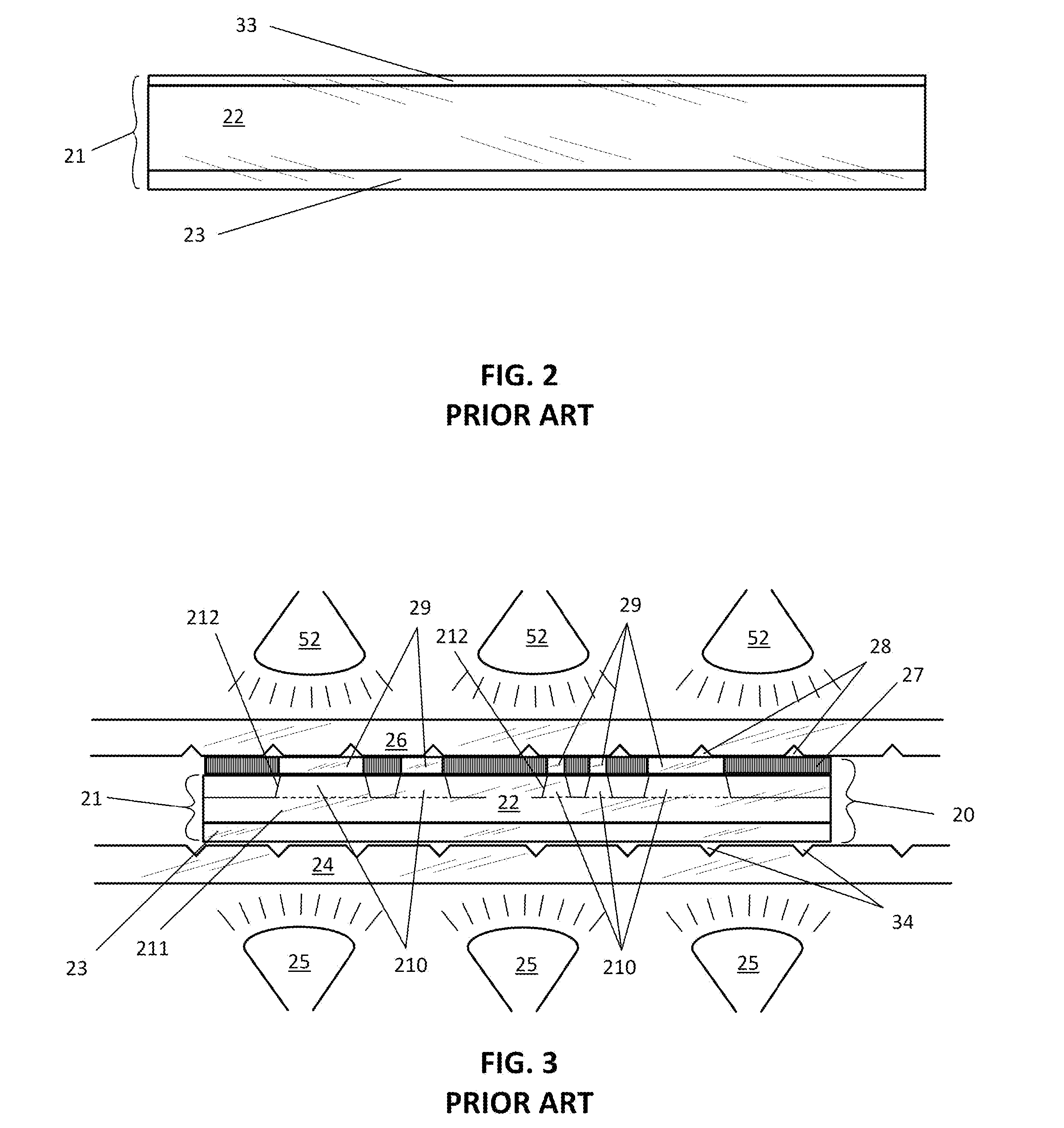
[0050]FIG. 4 is a magnified, not-to-scale cross-sectional view of the present invention, namely a solvent ink negative image 51 printed on the slip film 33 of a sheet photopolymer 21. The solvent ink is made in accordance with U.S. patent application Ser. No. 13 / 902,301, and is thus satisfactorily printed to the required opacity on the typical slip film material, polyester, e.g., polyethylene terephthalate (PET) using one print-head pass of an inkjet printer. While inkjet printing is the current technology of choice for precise additive imaging, the present invention applies to any method of ink application which allows the masking image to be applied in a single laydown. Eliminating the need for plural laydowns speeds the process of image creation but also removes any issues with registration of duplicate laydowns.

[0051]Moreover, using this embodiment, the entire relief image negative (see element 27 in FIG. 3) of the prior art is eliminated, along with the air-containing interface...

second embodiment

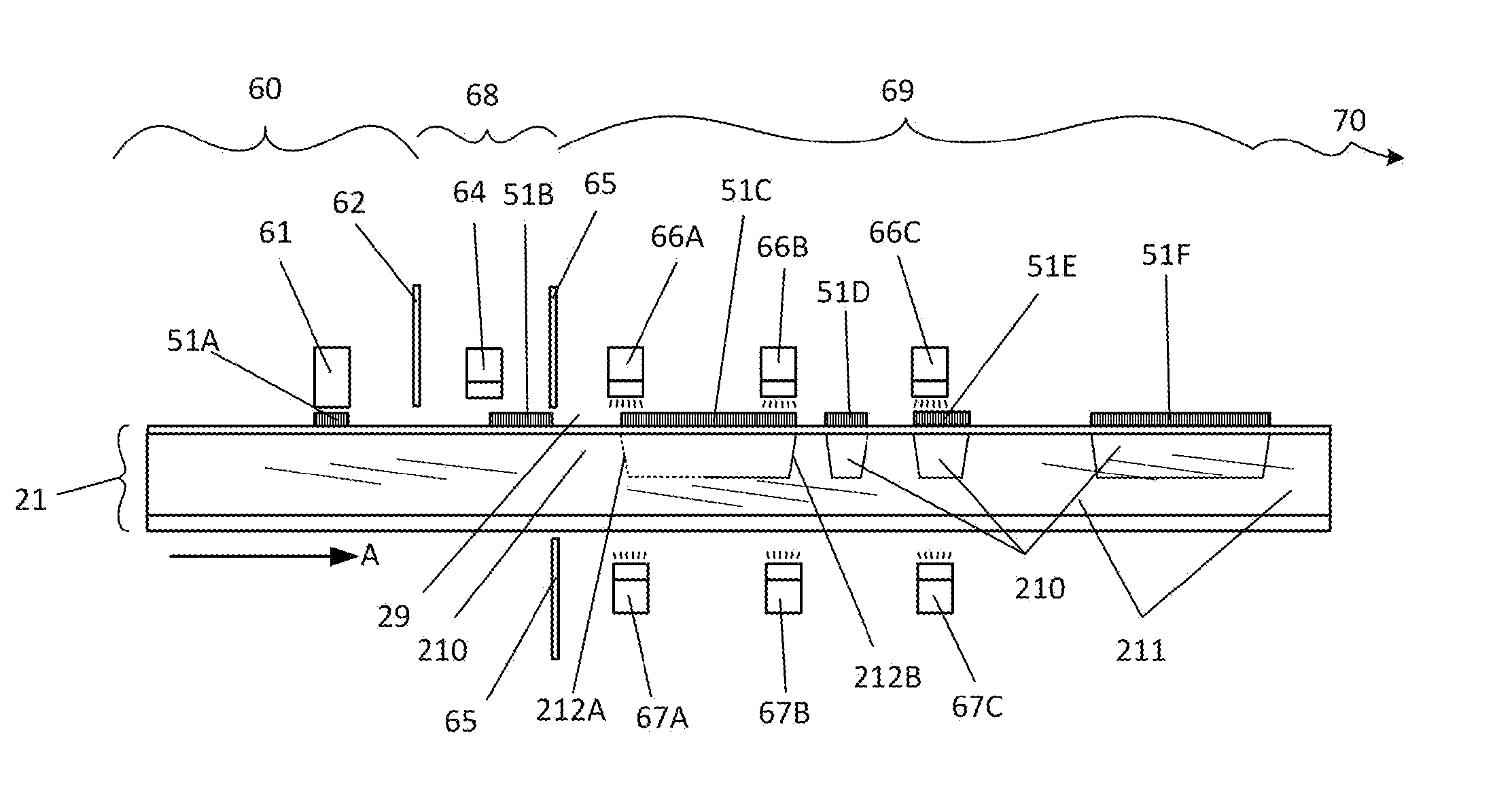
[0059]FIG. 5 is a magnified, not-to-scale cross-sectional view of the present invention, namely a schematic of a combined inkjet printing and relief image creating machine in the process of sequentially printing the laminate of FIG. 4 and producing a polymerized relief-imaged plate ready for post-processing. A fresh, unprinted sheet photopolymer 21, having been introduced into the inkjet printer portion 60 of this embodiment, is having relief negative image 51A printed on it by an inkjet printer head 61. The sheet polymer 21 is moving in the direction A while the printer head 61 moves back and forth in a direction toward and away from the viewer. Thus the image 51A represents a single pass of the head 61 toward the viewer (a single laydown of ink). When head 61 reaches its farthest point toward the viewer, sheet 21 will index in direction A and head 61 will move away from the viewer, laying down ink as programmed A stationary opaque baffle 62 prevents light from entering the printer...


PUM

PropertyMeasurementUnit
temperatureaaaaaaaaaa
surface temperatureaaaaaaaaaa
optical densityaaaaaaaaaa

Abstract

Flexography relief images are produced in currently-available sheet photopolymers by printing them with one inkjet printer pass using solvent-based inks without the need for an inkjet-receptive coating. A solvent ink that will adhere to the surface of the photopolymer slip film with no coating is used and, in embodiments, quick-dried to maximize image quality by heating the inked surface up to about 50° C. In embodiments, sheet photopolymer plates so masked and exposed can then be exposed to UV light in a modified printer that, in effect, transforms a batch process to a continuous one.

Description

[0001]This invention is in the field of printing, more specifically in the field of flexography and still more particularly the field of making flexographic printing plates from sheet photopolymer base plates.DESCRIPTION OF THE RELATED ART [0002]Flexographic printing is a printing process which uses a flexible rubber or photopolymer relief plate, prepared with raised areas called relief areas, corresponding to an image to be printed, and surrounded by lower areas called floor areas. The plate is typically secured to a revolving drum which is contacted by an anilox roll system to coat the relief areas with ink and subsequently press the inked areas against a moving sheet of, e.g., paper or corrugated box board. The flexible printing plates may alternatively be applied to plate mounts, e.g., hand stamps, or, potentially, non-planar surfaces other than drums.[0003]Images for flexographic printing are typically created by using a negative of an image to mask non-image areas on a layer o...

Claims


Application Information

Patent Timeline
Patent Type & Authority Applications(United States)
IPC IPC(8): B41C1/00G03F7/038G03F7/20
CPCB41C1/003G03F7/038G03F7/20C09D11/36C09D11/50B41M2205/14G03F7/092G03F7/2018G03F7/2022
Inventor MANEIRA, JOHN P.
Owner CHEMENCE
Why Eureka
Try Eureka