Method of Developing Latent Fingerprints

a fingerprint and latent technology, applied in the field of latent fingerprint development, can solve the problems of poor results and significant limitations of published methods, and achieve the effects of simple, reliable, and quick training

Inactive Publication Date: 2011-03-31
UNIV OF TECH SYDNEY
View PDF8 Cites 14 Cited by
  • Summary
  • Abstract
  • Description
  • Claims
  • Application Information

AI Technical Summary

Benefits of technology

[0021]It will be appreciated that embodiments of the invention avoid destruction or contamination of the fingerprint or substrate due to reagents and a clean process is offered which can either be laboratory operated or operated in situ to permit the collection and preservation of evidence. The invention lends itself to be implemented into current forensic workflows, such that subsequent development techniques can be applied to a sample that has been developed using the techniques embodied in this invention. Embodiments include those which can be performed by operators who can quickly be trained and provide a simple, reliable and cost effective methodology for fingerprint acquisition and processing.
[0022]Embodiments of the invention facilitate a clean, rapid and reliable system for obtaining suitable specimens outside a laboratory and even permits reliable, portable processing without the use of laboratory conditions and expense.

Problems solved by technology

Whereas such methods may be considered in some circumstances to have usefulness as a preliminary non-destructive testing technique, it is considered there are significant limitations and only poor results can be achieved with published methods.

Method used


Image

  • Method of Developing Latent Fingerprints
  • Method of Developing Latent Fingerprints
  • Method of Developing Latent Fingerprints

Examples


example 1

[0043]Hot air gun

[0044]A hot air gun (Leister Triac S Hot Air Blower) was calibrated using a thermocouple to measure the temperature of the air emitted at two distances from the device, namely 3 cm and 6 cm, for ten different heat settings spanning the full range. This corresponded to a temperature range of 45-360° C. at 6 cm and 60-535° C. at 3 cm. These were air temperatures and it is likely that paper at these distances only approached but probably did not reach these temperatures.

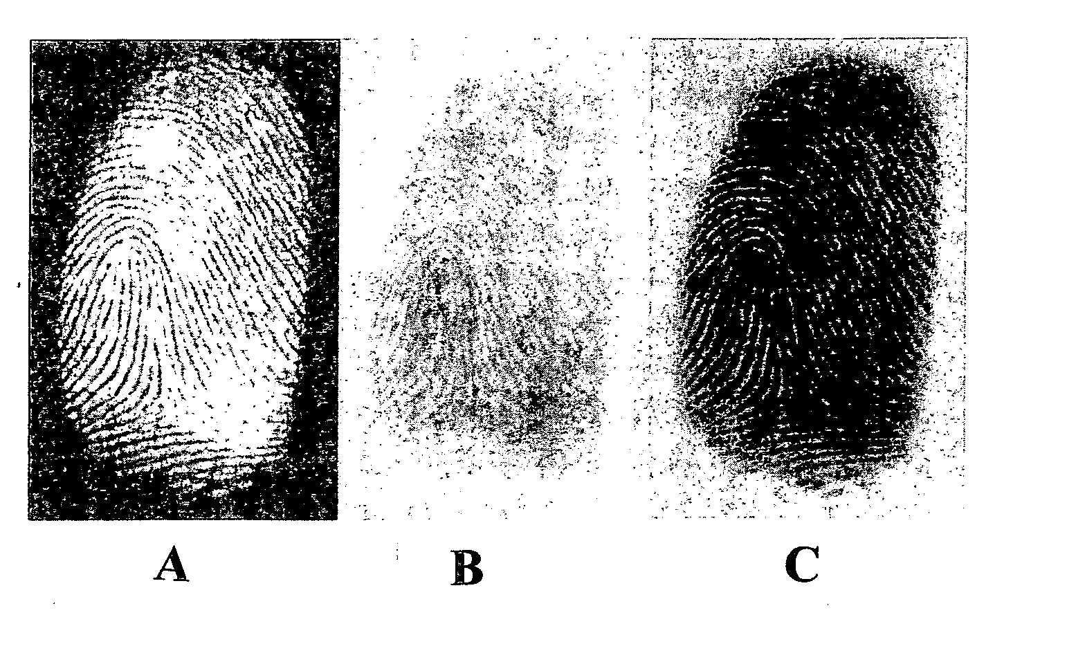
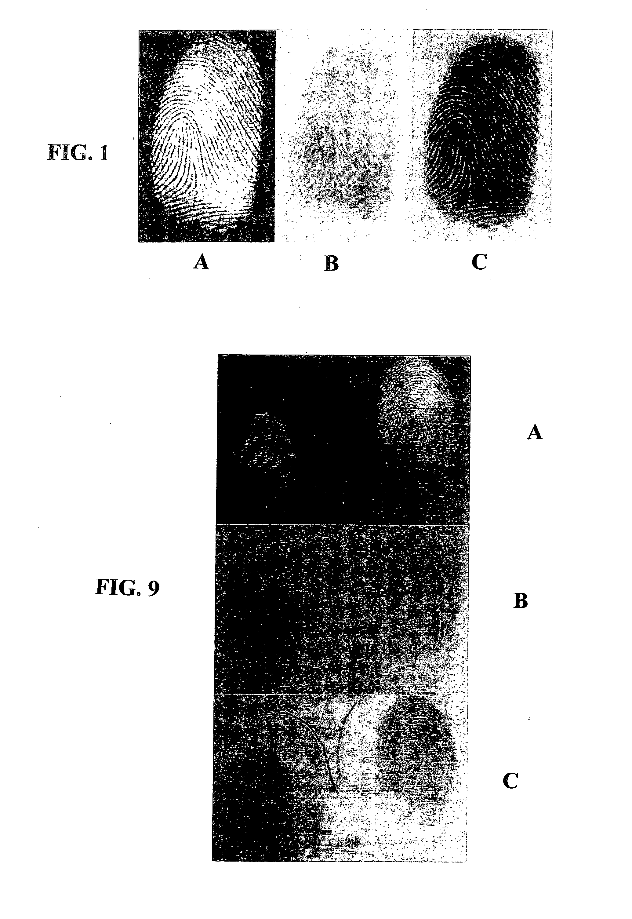
[0045]At a heating distance of 6 cm, an air temperature of 160° C. did not give rise to any fluorescent or visible development of fingerprints on white copy paper after heating for 8 min. Fingerprint development started to be observed at temperatures above about 220° C., and at 245° C., fluorescent prints were developed after 6 min of heating. By 310° C., fluorescent fingerprints were developed after 45 sec, turning visible (brown) after about 1 min. This process accelerated with further increases in te...

example 2

[0048]Muffle furnace

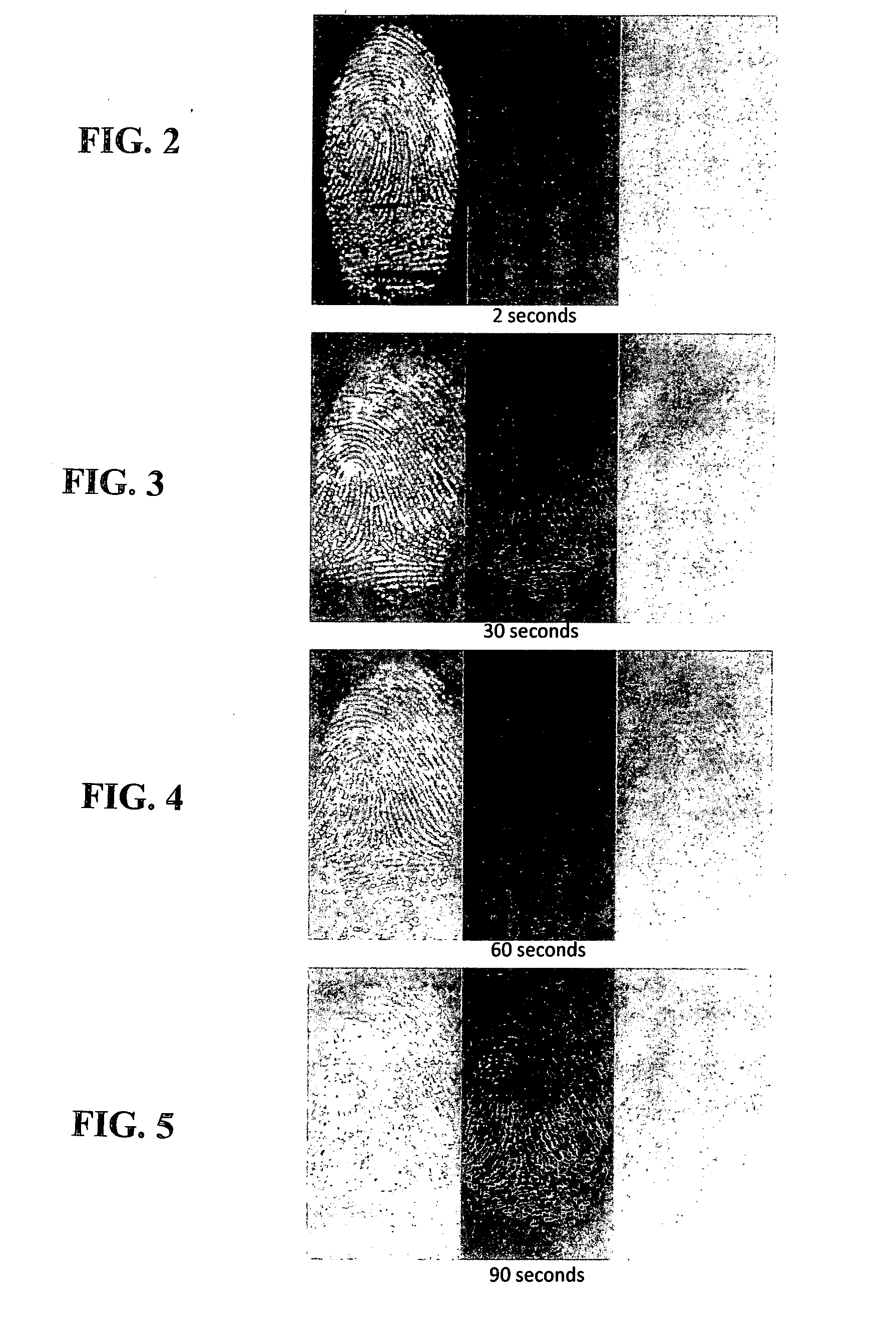
[0049]A wire embedded element furnace (made by B and L Tatlow) was used. The nominal temperature of the muffle furnace was set in the vicinity of 300° C.; monitoring of the actual temperature with a thermocouple showed that temperature variation was ±10° C. Since the door had to be opened to admit the sample, the “initial” temperature at which the paper sample was heated was generally 20-30° C. degree cooler than nominal. For an initial temperature of about 300° C., the times for fluorescent and then subsequent visible fingerprint development were 10 seconds and 20 seconds respectively. Some general observations were:

[0050]Visible prints could be developed on every type of paper tested, although the development of fluorescent prints prior to visible observation was not observed for some copy paper colors.

[0051]Using the furnace, fingerprints on crumpled paper could be developed.

[0052]One week-old and seven week-old prints could be developed in the furnace.

example 3

[0053]GC Oven

[0054]A Hewlett Packard 5890 Series II Gas Chromotography (GC) oven was used. Samples (white copy paper) developed in the GC oven were subjected to a linear temperature ramp taking them from 100 to 300° C. at rates which varied from 5 degree C / min to 70 degrees C / min. All of these experiments were conducted until visible prints could be observed on the paper. In general, no visible prints were observed before 220° C., and the best prints were obtained with the fastest heating rate of 70 degrees C / min, although all of the ramps developed fingerprints.

[0055]A fingerprint aged for two months was also successfully developed in the GC oven.


PUM


Abstract

Latent fingerprints on a porous substrate such as paper are developed for viewing and recordal by applying heat to cause the fingerprint to be clearly viewed under radiation to cause the fingerprint to fluorescence (e.g. a few seconds heating with air or client contact with a heated device at around 260° C.) and viewing under e.g. light of 200 nm to 550 nm with a filter in the yellow to orange wavelength region. Alternatively more extended heating can render the fingerprint assemble under ultraviolet light, and under yet more extended heating permits viewing under white light.

Description

TECHNICAL FIELD[0001]This invention relates to a method of developing latent fingerprints and particularly to developing fingerprints on porous surfaces.[0002]In this specification “porous surfaces or substrates” refers to paper, paper-like, other cellulose-based products (such as wood or other natural fibres, materials or fabrics such as cotton-based fabrics) and similar products, materials or fabrics susceptible to processing by the methods described herein.BACKGROUND OF THE INVENTION [0003]One known technique for detection of latent fingerprints on surfaces which may be porous (such as paper) is the use of optical imaging for example under ultraviolet light.[0004]Another reported approach is to bake a sheet of paper carrying a latent fingerprint so as to develop an image.[0005]Whereas such methods may be considered in some circumstances to have usefulness as a preliminary non-destructive testing technique, it is considered there are significant limitations and only poor results c...

Claims


Application Information

Patent Timeline
Patent Type & Authority Applications(United States)
IPC IPC(8): A61B5/117
CPCA61B5/1172G01N21/71G01N21/6456
Inventor REEDY, BRIANTAHTOUH, MARKBROWN, ADAMSONG, DI FEISOMMERVILLE, DANIELSHIMMON, RONALD
Owner UNIV OF TECH SYDNEY
Why Eureka
Try Eureka