Piezoelectric filter, communication device, and method for manufacturing communication device

a technology of communication device and piezoelectric filter, which is applied in piezoelectric/electrostrictive transducers, device material selection, generators/motors, etc., can solve the problems of deterioration of resonator characteristics, difficulty in doing, and inability to readily increase productivity, etc., to achieve excellent electrical characteristics, stable filter characteristics, and high productivity

Inactive Publication Date: 2005-03-15
MURATA MFG CO LTD
View PDF10 Cites 10 Cited by
  • Summary
  • Abstract
  • Description
  • Claims
  • Application Information

AI Technical Summary

Benefits of technology

In order to solve the various problems described above, preferred embodiments of the present invention provide a piezoelectric filter, a communication device including such a piezoelectric filter, and a method for manufacturing the piezoelectric filter, wherein the piezoelectric filter has very high productivity, excellent electrical characteristics and very stable filter characteristics against temperature change.
Since the upper and lower electrodes are in contact with the piezoelectric thin-film, change in the resonant frequency with respect to the thickness of the upper and lower electrodes can be increased. Therefore, the ratio of the thickness of the piezoelectric thin-film to the thickness of the upper or lower electrodes is not significantly changed, and the temperature characteristics of the resonant frequency of piezoelectric resonator portions having a relatively low resonant frequency and other piezoelectric resonator portions are not significantly changed, thereby obtaining the stable filter characteristics against change in temperature.

Problems solved by technology

Therefore, the selectivity of the film formation must be improved but it is difficult to do so which presents a significant problem.
Therefore, there is a problem in that the productivity cannot be readily increased.
Therefore, there is a risk that the characteristics of the resonator are deteriorated.
On the other hand, in the configuration disclosed in U.S. Pat. No. 5,910,756, since it is difficult to widely control the resonant frequency with respect to the thickness of the SiO2 layers, the second SiO2 layer must have a certain thickness in order to obtain a desired difference between the frequency of resonators connected in parallel and that of resonators connected in series when a ladder filter is prepared.
Therefore, there is a problem in that the filter characteristics are significantly changed.

Method used


Image

  • Piezoelectric filter, communication device, and method for manufacturing communication device
  • Piezoelectric filter, communication device, and method for manufacturing communication device
  • Piezoelectric filter, communication device, and method for manufacturing communication device

Examples


first preferred embodiment

A configuration of a piezoelectric filter according to a first preferred embodiment will now be described with reference to FIGS. 1-3.

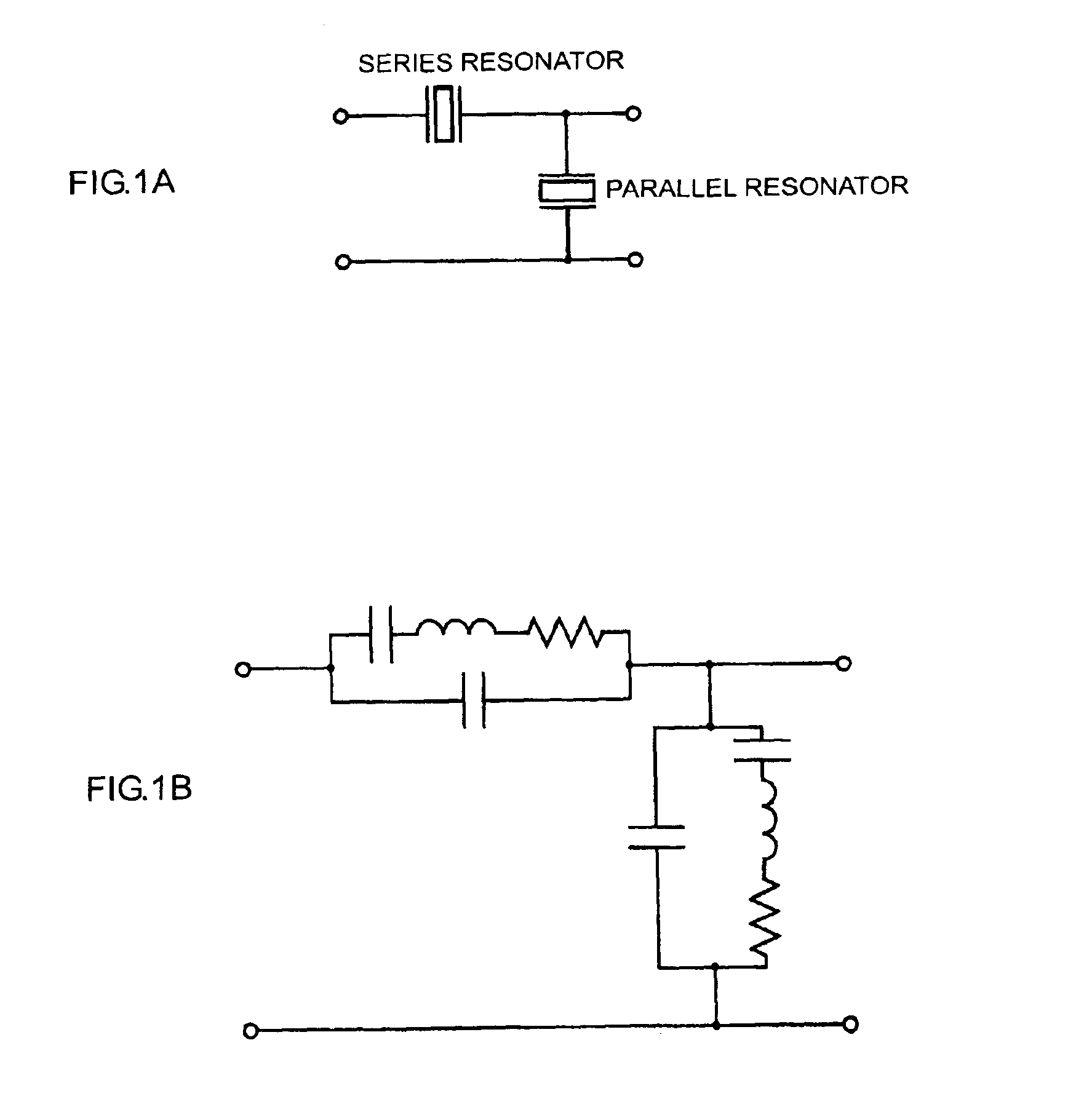
FIG. 1A is an illustration showing a circuit of a simple ladder-type piezoelectric filter and FIG. 1B is an illustration showing an equivalent circuit thereof. Both series and parallel resonators included in the filter are a piezoelectric type. As shown in FIG. 1B, these resonators each have an equivalent circuit including a capacitor, an inductor, and a resistor connected in series and another capacitor connected in parallel. The capacitor and the inductor connected in series generate series resonance, and the capacitor and the inductor connected in parallel generate parallel resonance.

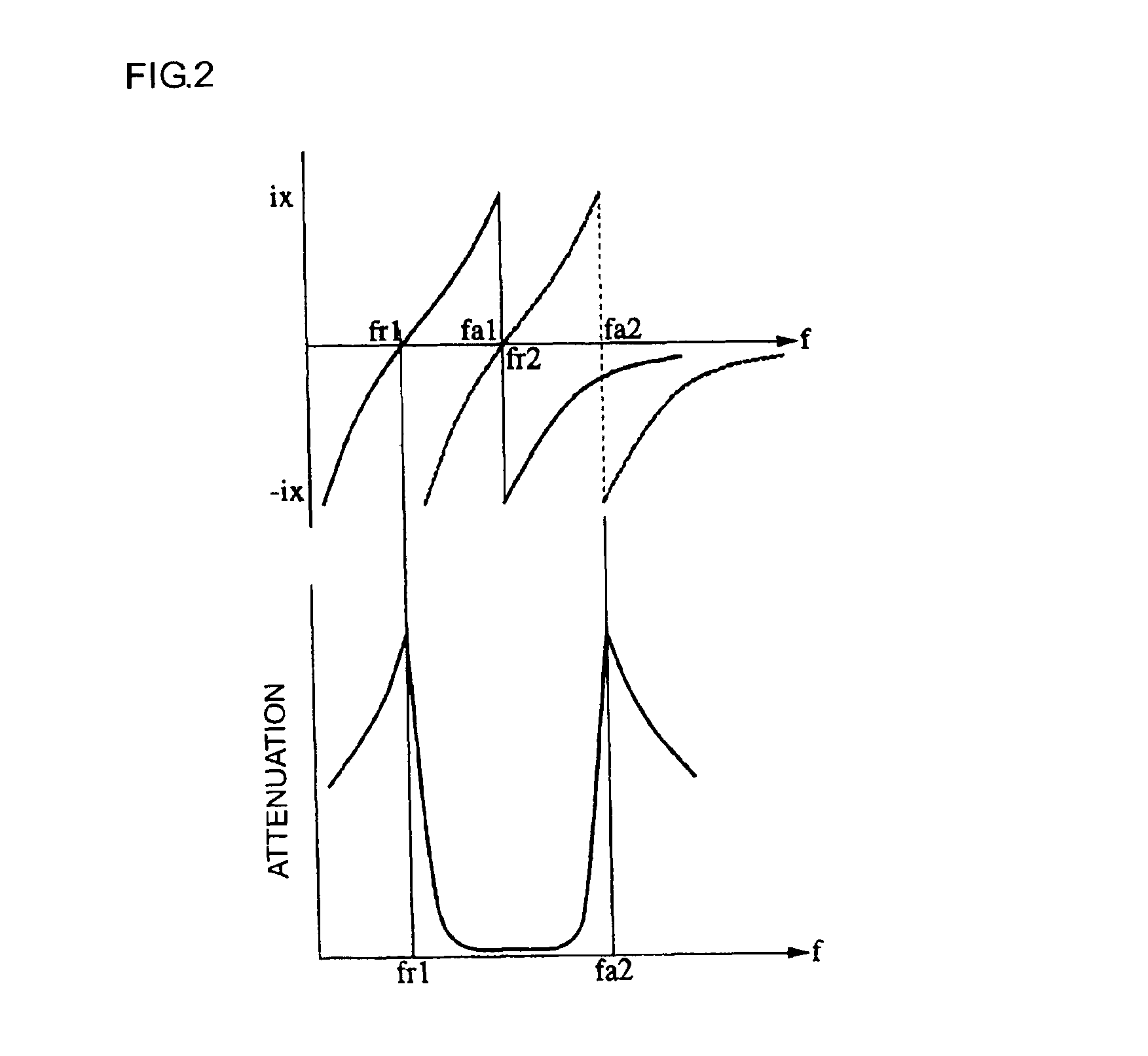
FIG. 2 shows reactance characteristics of the series resonance generated by the series resonator and the parallel resonance generated by the parallel resonator in a superimposed manner. In the figure, the solid line represents the characteristic of the parallel resonat...

second preferred embodiment

Next, a configuration of another piezoelectric filter according to a second preferred embodiment and a manufacturing method thereof will now be described with reference to FIG. 6.

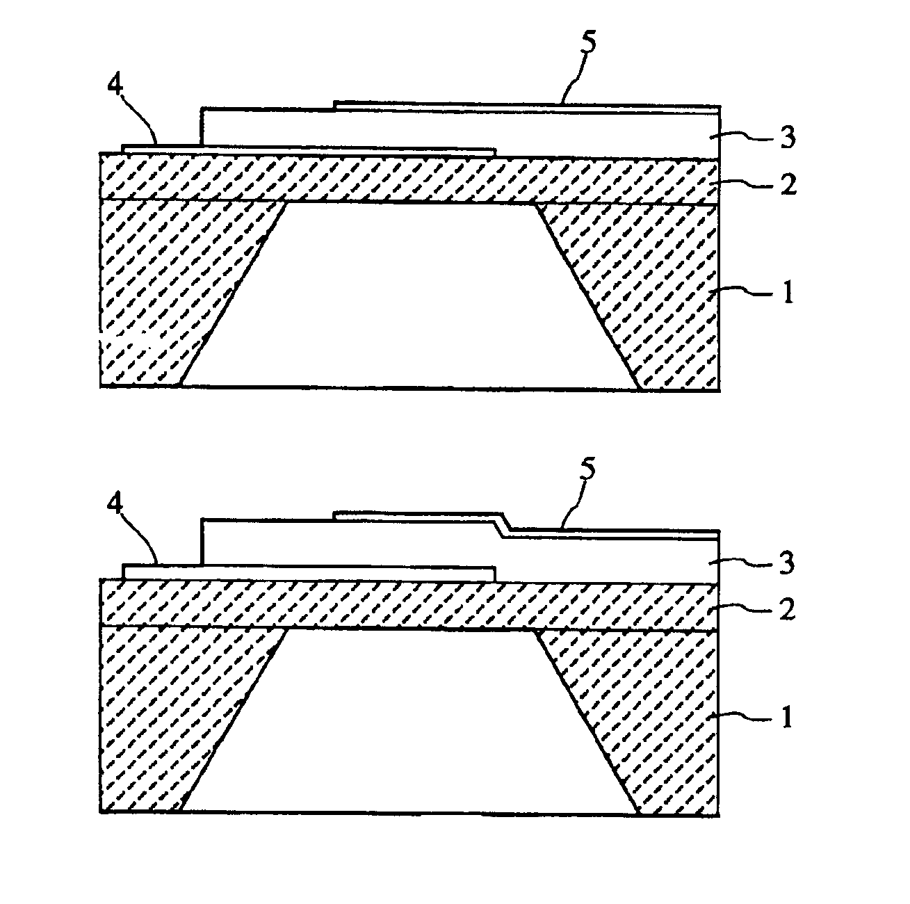
FIG. 6A is a sectional view showing a series resonator portion and FIG. 6B is a sectional view showing a parallel resonator portion. These resonator portions are formed on the same substrate and are separately shown in the figures, however.

The series resonator portion has the same structure as that shown in FIG. 3A. The upper electrode 5 of the parallel resonator portion has a thickness that is larger than that of the series resonator portion.

The thickness of upper electrode 5 is adjusted by performing vacuum vapor deposition or sputtering two times using a metal mask in the same manner as in the first preferred embodiment of the present invention.

In the series and parallel resonator portions, the SiO2 layer 2, the piezoelectric thin-film 3, and the lower and upper electrodes 4 and 5 define a resonant regio...

third preferred embodiment

Next, a configuration of a ladder-type piezoelectric filter according to a third preferred embodiment will now be described with reference to FIG. 7.

FIG. 7A is an illustration showing a circuit of the ladder-type piezoelectric filter including two series resonators and three parallel resonators, and FIG. 7B is an illustration showing the arrangement of the series and parallel resonators and upper and lower electrodes thereof. In FIG. 7B, the lower electrodes are represented with the solid lines and the upper electrodes are represented with the broken lines. Both the series and parallel resonators are a piezoelectric type. As described in the first preferred embodiment, the series and parallel resonators generate series and parallel resonances, respectively. The filter functions well by adjusting the resonant frequency of the series and parallel resonators.

As shown in FIG. 7, the ladder-type piezoelectric filter has first, second, and third parallel resonators 101, 103, and 105 and f...


PUM

PropertyMeasurementUnit
piezoelectricaaaaaaaaaa
frequencyaaaaaaaaaa
thicknessaaaaaaaaaa

Abstract

A piezoelectric filter includes a plurality of piezoelectric resonator portions each having a substrate, an SiO2 layer, a piezoelectric thin-film, a lower electrode, and an upper electrode. The plurality of piezoelectric resonator portions include piezoelectric resonator portions having a relatively low frequency, and the lower electrodes of the piezoelectric resonator portions having a relatively low frequency have a thickness larger than that of lower electrodes of other piezoelectric resonator portions. A ladder-type piezoelectric filter, which is one of the communication devices, includes a plurality of parallel resonators and series resonators.

Description

BACKGROUND OF THE INVENTION1. Field of the InventionThe present invention relates to a piezoelectric filter including a piezoelectric resonator having a substrate, such as a silicon wafer, and a piezoelectric thin-film disposed on the substrate, and also relates to a communication device and a method for manufacturing the piezoelectric filter.2. Description of the Related ArtPiezoelectric resonators having a substrate, such as a silicon wafer, and a piezoelectric thin-film disposed on the substrate are disclosed in Japanese Unexamined Patent Application Publication No. 58-121815 and U.S. Pat. No. 5,910,756.A piezoelectric resonator disclosed in Japanese Unexamined Patent Application Publication No. 58-121815 has a substrate having a recessed portion, a piezoelectric thin-film having a pair of electrodes and disposed on a surface of the substrate, and a frequency-adjusting thin-film disposed in the recessed portion located on the back of the surface of the substrate and located at an...

Claims


Application Information

Patent Timeline
Patent Type & Authority Patents(United States)
IPC IPC(8): H03H9/00H03H9/58H01L41/08H01L41/18H01L41/22H01L41/29H03H3/02H01L41/09H03H3/04H03H9/02H03H9/17H03H9/60
CPCH03H3/04H03H9/174H03H9/605Y10T29/42H03H2003/0428H03H2003/0471
Inventor TAKEUCHI, MASAKIKAWAMURA, HIDEKI
Owner MURATA MFG CO LTD
Why Eureka
Try Eureka