Wireless power and communications cross-bar switch

a cross-bar switch and wireless technology, applied in the field of wireless power and communications cross-bar switches, can solve the problems of high cost of method and system described in u.s. pat. no. 4,839,644 and the difficulty of using a cabl

Inactive Publication Date: 2005-03-15
SHELL OIL CO
View PDF135 Cites 14 Cited by
  • Summary
  • Abstract
  • Description
  • Claims
  • Application Information

AI Technical Summary

Benefits of technology

Another general application of the present invention is in a non-blocking switching network in which any input line (N) may be connected to a plurality of one or more output lines (M), where the number of input lines (N) does not exceed the number of output lines (M). An extreme instance of this application is where N=1 and M is an arbitrary number, thereby defining a star-shaped, or hub and spoke, power and communication topology. Multiple chokes can be used to selectively partition and route power and information to any desired subset of the M output lines. Again, in the event that partial power and communication conveyance is desired, smaller chokes may be employed. Regardless of the application, installation of the induction chokes in selective positions provides for a flexible, reconfigurable power and communications routing mechanism within a piping structure.

Problems solved by technology

It is undesirable and in practice difficult to use a cable along the tubing string either integral with the tubing string or spaced in the annulus between the tubing and the casing because of the number of failure mechanisms are present in such a system.
But such standard electrical conduits can be difficult to route at great depths, around turns for deviated wells, along multiple branches for a well having multiple lateral branches, and / or in parallel with coil production tubing.
Therefore, the method and system described in U.S. Pat. No. 4,839,644 is expensive, has problems with brine leakage into the casing, and is difficult to use for downhole two-way communication.
Other downhole communication concepts, such as mud pulse telemetry (U.S. Pat. Nos. 4,648,471 and 5,887,657), have shown successful communication at low data rates but are of limited usefulness as a communication scheme where high data rates are required or it is undesirable to have complex, mud pulse telemetry equipment downhole.
Such protection chokes work well for their intended purpose, but do not operate to define a power or communication circuit.

Method used


Image

  • Wireless power and communications cross-bar switch
  • Wireless power and communications cross-bar switch
  • Wireless power and communications cross-bar switch

Examples


Embodiment Construction

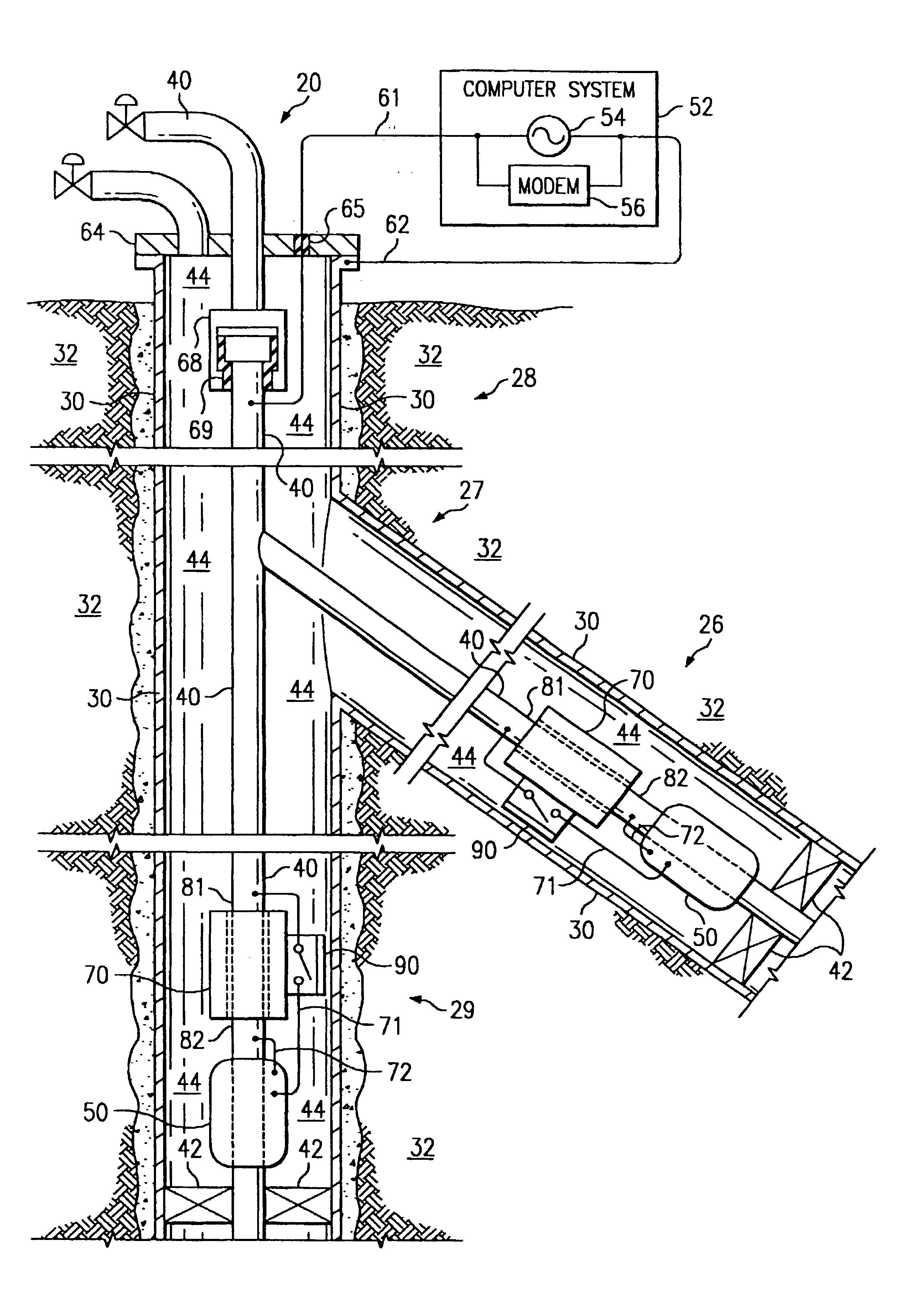
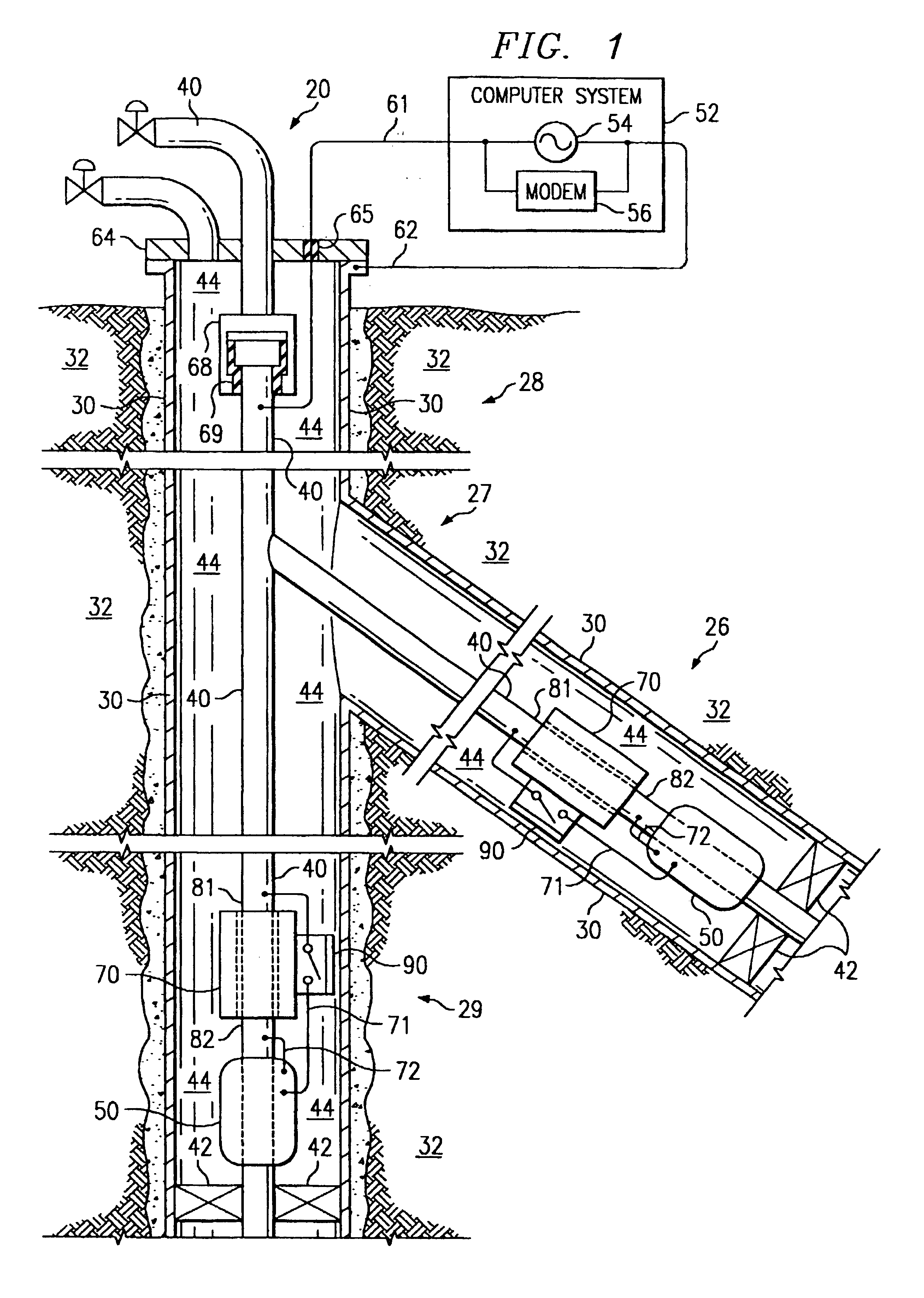
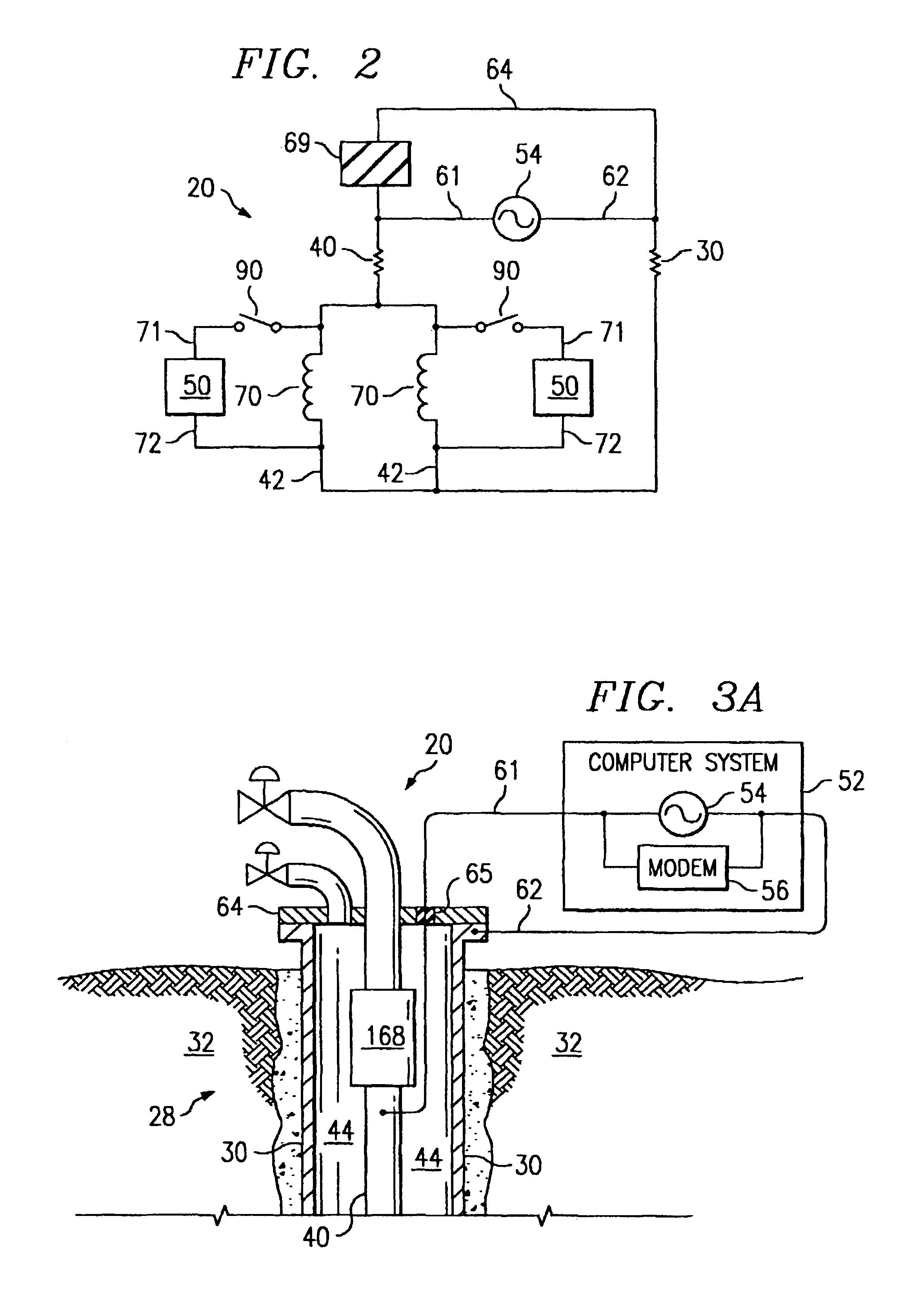
Referring now to the drawings, wherein like reference numbers are used herein to designate like elements throughout the various views, preferred embodiments of the present invention are illustrated and further described, and other possible embodiments of the present invention are described. The figures are not necessarily drawn to scale, and in some instances the drawings have been exaggerated and / or simplified in places for illustrative purposes only. One of ordinary skill in the art will appreciate the many possible applications and variations of the present invention based on the following examples of possible embodiments of the present invention, as well as based on those embodiments illustrated and discussed in the Related Applications, which are incorporated by reference herein to the maximum extent allowed by law.

As used in the present application, a “piping structure” can be one single pipe, a tubing string, a well casing, a pumping rod, a series of interconnected pipes, rod...


PUM


Abstract

A petroleum well for producing petroleum products that incorporates a system adapted to controllably route communications and/or electrical power having a time-varying current through a piping structure in the well, and methods of producing petroleum products use such a well, are provided by the present invention. The system comprises a first induction choke, a second induction choke, and a controllable switch. The first induction choke is located about a portion of a first branch of the piping structure. The second induction choke is located about a portion of a second branch of the piping structure. The controllable switch having two switch terminals. A first of the switch terminals I is electrically connected to the piping structure on a junction side of the induction chokes. The first and second branches of the piping structure intersect on the junction side of the induction chokes. A second of the switch terminals is electrically connected to the piping structure on another side of at least one of the induction chokes.

Description

BACKGROUND1. Field of the InventionThe present invention relates to a system for controllably routing power and / or communications through a network of interconnected members of a piping structure or a metal structure using individually controllable switches and induction chokes. In one aspect, it relates to a petroleum production well and a method of operating the well to provide a controllable downhole switching network for routing power and / or communications to downhole devices.2. Description of Related ArtSeveral methods have been devised to place controllable valves and other devices and sensors downhole on a tubing string in a well, but all such known devices typically use an electrical cable along the tubing string to power and communicate with the devices and sensors. It is undesirable and in practice difficult to use a cable along the tubing string either integral with the tubing string or spaced in the annulus between the tubing and the casing because of the number of failu...

Claims


Application Information

Patent Timeline
Patent Type & Authority Patents(United States)
IPC IPC(8): E21B47/12E21B41/00G01V11/00E21B17/00E21B34/06E21B34/08E21B34/16E21B43/12E21B43/14E21B47/13H04B5/00
CPCE21B17/003E21B34/066E21B34/08E21B34/16G01V11/002E21B43/123E21B43/14E21B47/122E21B41/0035E21B47/13
Inventor VINEGAR, HAROLD J.HAASE, MARK CHRISTOPHER
Owner SHELL OIL CO
Why Eureka
Try Eureka