Beam broadening with maximum power in array transducers

a technology of array transducers and beam broadening, applied in the field of array transducers, can solve the problems of increasing frequency, increasing frequency, and reducing the power output of the array, and achieving the effect of increasing frequency

Inactive Publication Date: 2005-03-15
RAYTHEON BBN TECH CORP
View PDF9 Cites 2 Cited by
  • Summary
  • Abstract
  • Description
  • Claims
  • Application Information

AI Technical Summary

Problems solved by technology

Since not all the available elements are being driven to maximum or even appreciable amplitude, the power output of the array is reduced and this reduction becomes more severe with increasing frequency.

Method used


Image

  • Beam broadening with maximum power in array transducers
  • Beam broadening with maximum power in array transducers
  • Beam broadening with maximum power in array transducers

Examples


Embodiment Construction

Reference will now be made in detail to the present embodiments of the invention, examples of which are illustrated in the accompanying drawings. Wherever possible, the same reference numbers will be used throughout the drawings to refer to the same or like parts.

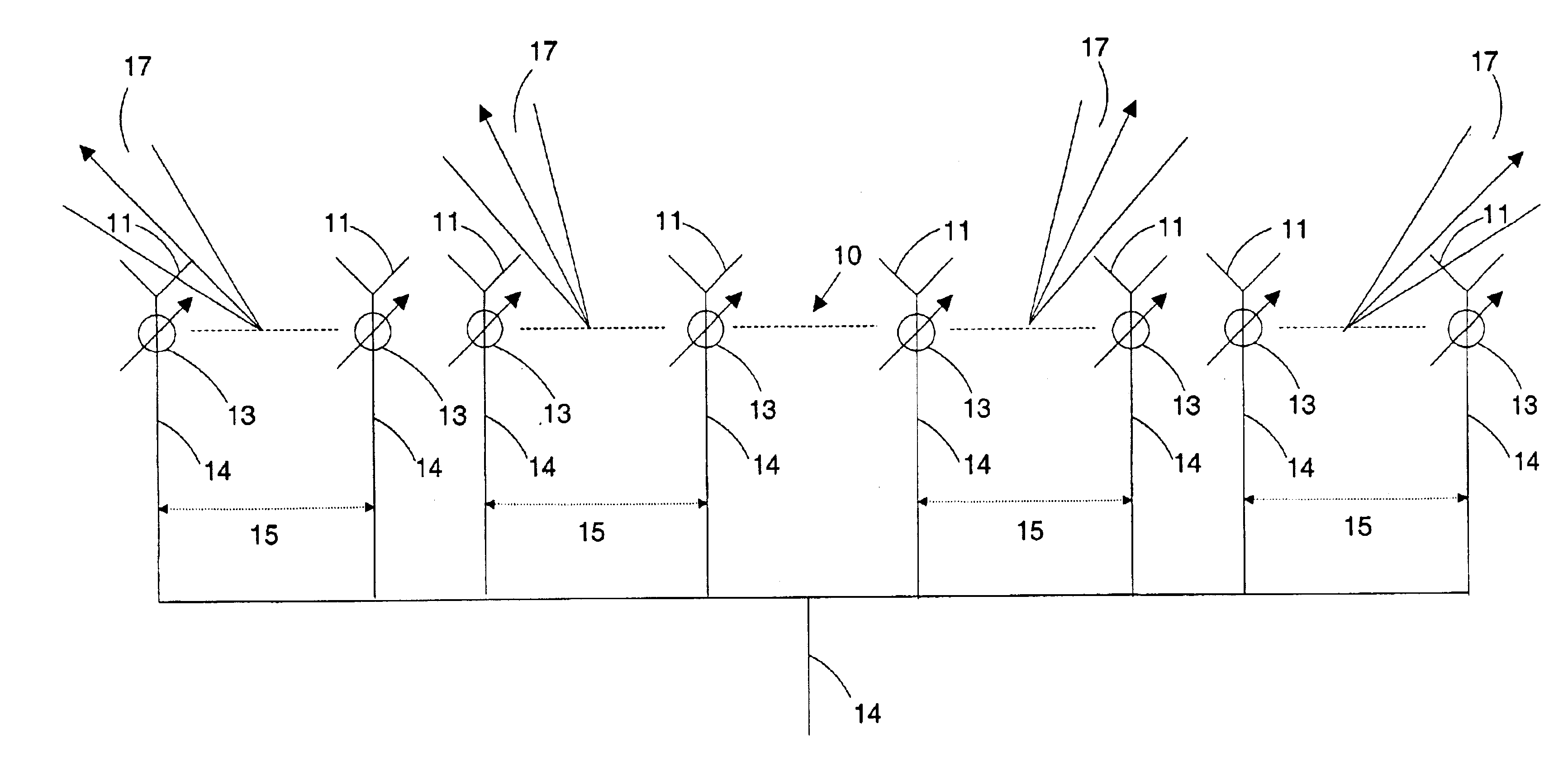
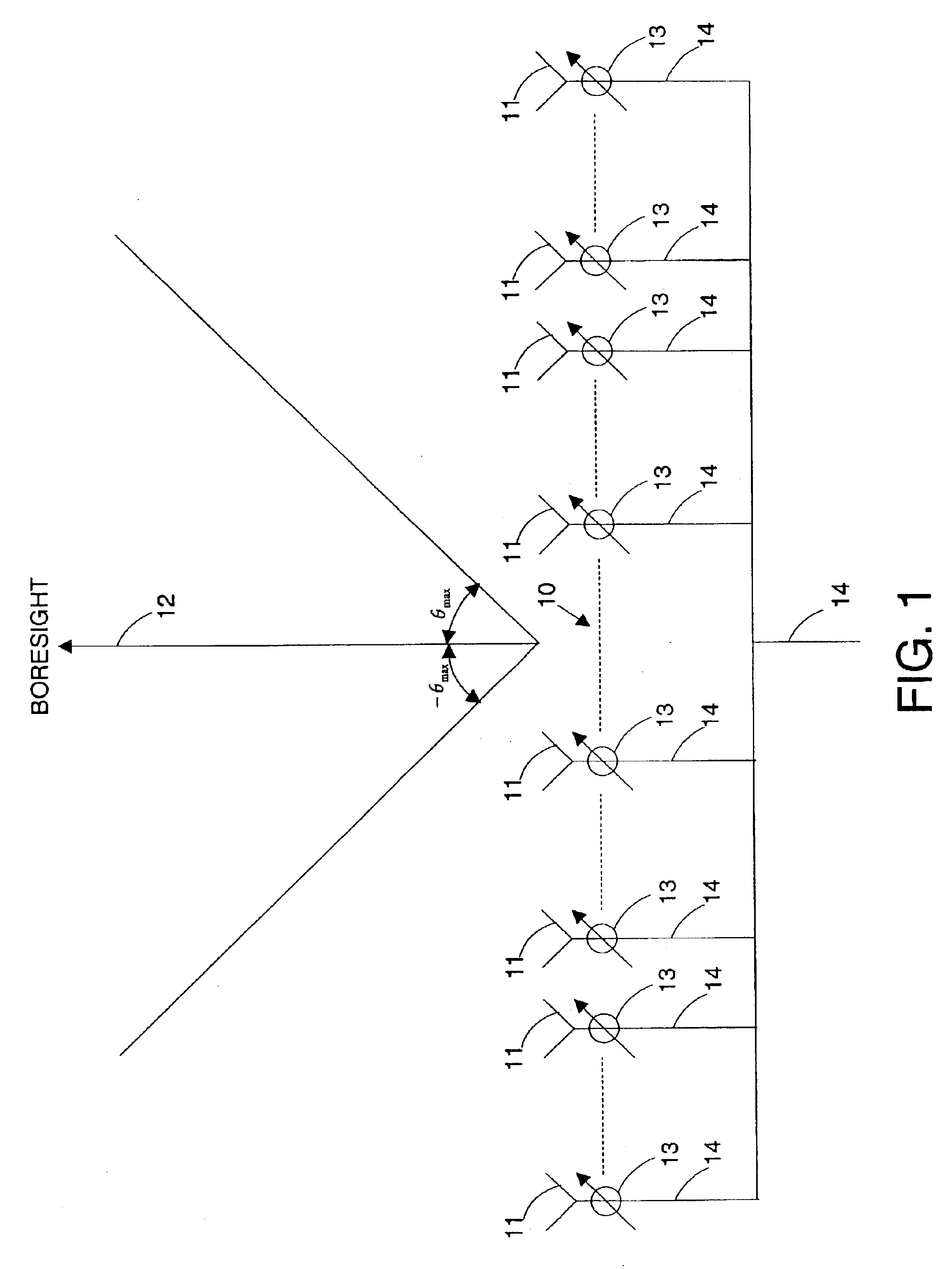
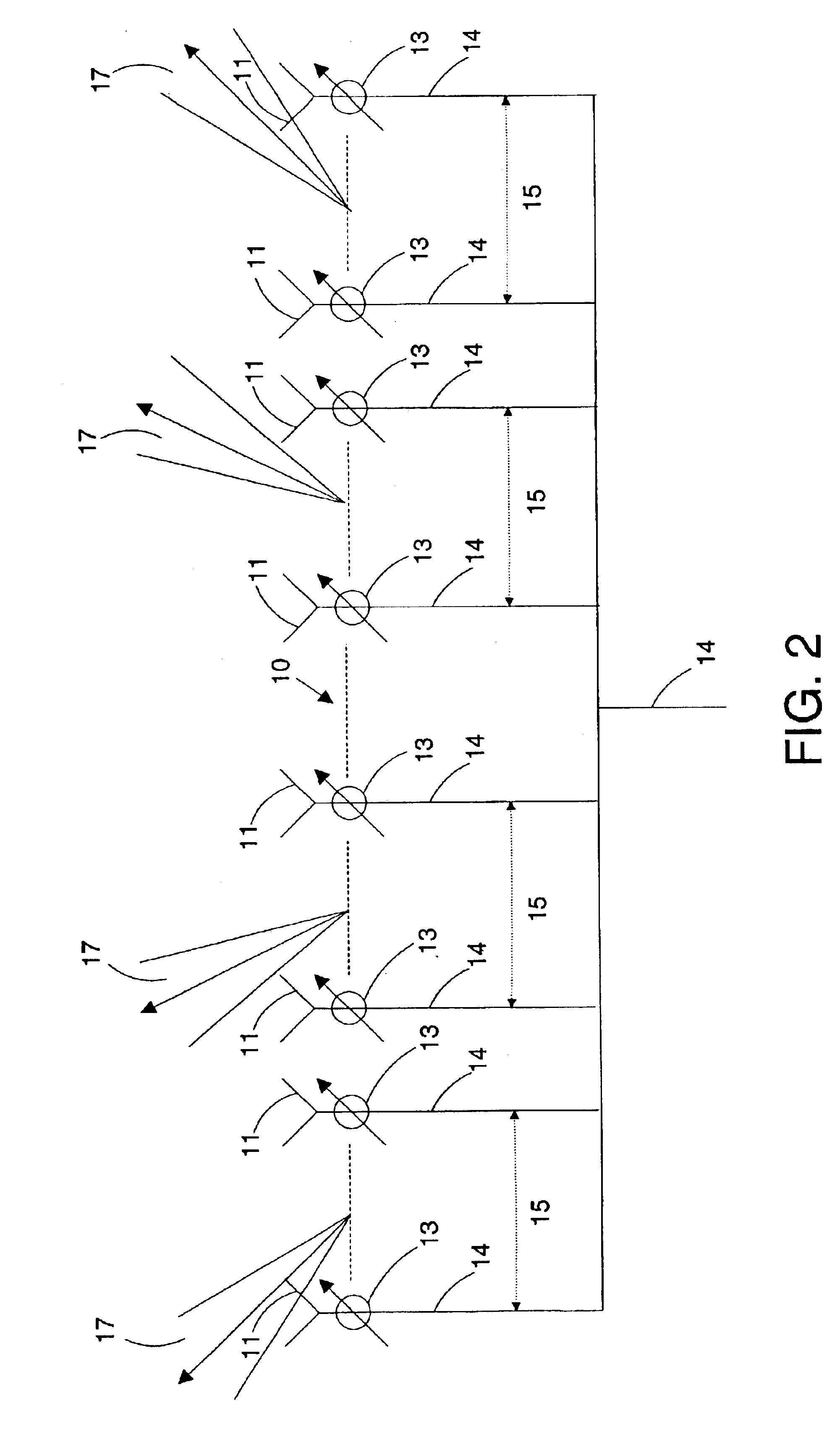
In FIG. 1, an array transducer 10 includes a plurality of radiating elements 11. Signals 14 are fed to the plurality of radiating elements 11 through phase shifters 13. The common input signal 14 can be a voltage that drives radiating elements 11. The radiating element 11 can be an electro-mechanical device that converts, for example, electric power to sound power.

Each of phase shifters 13 shifts the phase of the input signal 14 fed to the plurality of radiating elements 11. A phase shifter for making a directional array of radiating elements is known in the art. See for example, John L. Brown, Jr. and Richard O. Rowlands, “Design of Directional Arrays,” Journal of the Acoustical Society of America, Vol. 31, No. 12, pp. 163...


PUM


Abstract

A system and method to provide maximum power over large angular sectors using an array of transducers is disclosed. Array segments of transducers and phase shifters form a beam from each of the array segments, wherein the set of beams overlap to form a large sector coverage beam. The phase of each of the signals fed to the radiating elements is shifted, such that the difference between beam point directions of the beams of two adjacent array segments is substantially equal to one half of the sum of the beamwidths of the beams of the two adjacent array segments. The phase of each of the signals fed to the radiating elements may also be shifted in proportion to the square of the distance between one end of the array of transducers and the position of each of the plurality of radiating elements.

Description

FIELD OF THE INVENTIONThe invention relates in general to sound and electromagnetic transmission systems and methods, and in particular to array transducers in which the transmit or receive beamwidth is broadened while maintaining or maximizing transmit power or receive sensitivity.BACKGROUND OF THE INVENTIONIn electromagnetic or sound transmission systems, an array transducer uses an array of simple transducers. Each transducer forming the array is known as an element of the array. The signals emitted from the elements are linearly combined as a weighted sum to form a receive array. A common signal is fed to the elements and weighted to form a transmit array. The process of combining the signals emitted from or fed to different elements is known as beam forming. When signals are combined without any gain and phase change, the direction in which the array has maximum response is perpendicular to the line joining all elements of a straight linear array.The signals from or the common ...

Claims


Application Information

Patent Timeline
Patent Type & Authority Patents(United States)
IPC IPC(8): H01Q3/26H01Q21/22H04R1/40
CPCH01Q3/26H01Q21/22H04R1/403H04R2430/20H04R2201/403H04R2201/405
Inventor BERKMAN, EVAN FRANK
Owner RAYTHEON BBN TECH CORP
Why Eureka
Try Eureka