Echo processing apparatus

a processing apparatus and echo technology, applied in the field of echo processing apparatus, can solve the problems of non-linear distortion of the echo signal, deterioration of the calculation accuracy of the adaptive filter coefficient calculated by the adaptive filter b>8/b>, and large difference between the pseudo echo signal to be generated and the echo signal, so as to achieve the effect of easy handling

Inactive Publication Date: 2005-03-15
MITSUBISHI ELECTRIC CORP
View PDF9 Cites 24 Cited by
  • Summary
  • Abstract
  • Description
  • Claims
  • Application Information

AI Technical Summary

Benefits of technology

It is thereby possible to extract the low-frequency component in the digital signal with a simple configuration and it is not necessary to replace the current low-pass filter in the double-talk detector with new one according to the change of the cutoff-frequency caused by replacing a kind of the speaker. Thus, it is easily to cope with the change of the cutoff-frequency by rewriting the set-frequency stored in the memory.

Problems solved by technology

In this case, a non-linear distortion occurs in the echo signal inputted through the microphone and the calculation accuracy of the adaptive filter coefficient calculated by the adaptive filter 8 is thereby deteriorated.
Further, there is a drawback in which the difference between the pseudo echo signal to be generated and the echo signal becomes large, and the amount of the echo suppression becomes reduced.
In a case in which a high-pass filter is inserted between the D / A converter and the amplifier at the received signal side, it is difficult to match the frequency components of this high-pass filter and both the high-pass filters placed before the adaptive filter and before the adder because the purpose to suppress the low frequency component is different between those high-pass filters.
As a result, the drawback occurs that the characteristic of the low frequency component is greatly different between the received signal to be inputted to the adaptive filter and the echo signal to be inputted to the microphone, this deteriorates the calculation accuracy of the adaptive filter coefficient and the difference between the pseudo echo signal and the echo signal becomes large, and the amount of the echo suppression is thereby reduced.
Thus, the conventional echo cancellers involve the drawback in which there is a possibility to occur the wrong judgment because it is difficult to distinct the single-talk and the double-talk apparently.
As a result, the wrong judgment to halt and start the update of the adaptive filter coefficient occurs, so that the calculation accuracy of the adaptive filter coefficient is deteriorated and the amount of the echo suppression is thereby reduced.

Method used


Image

  • Echo processing apparatus
  • Echo processing apparatus
  • Echo processing apparatus

Examples


first embodiment

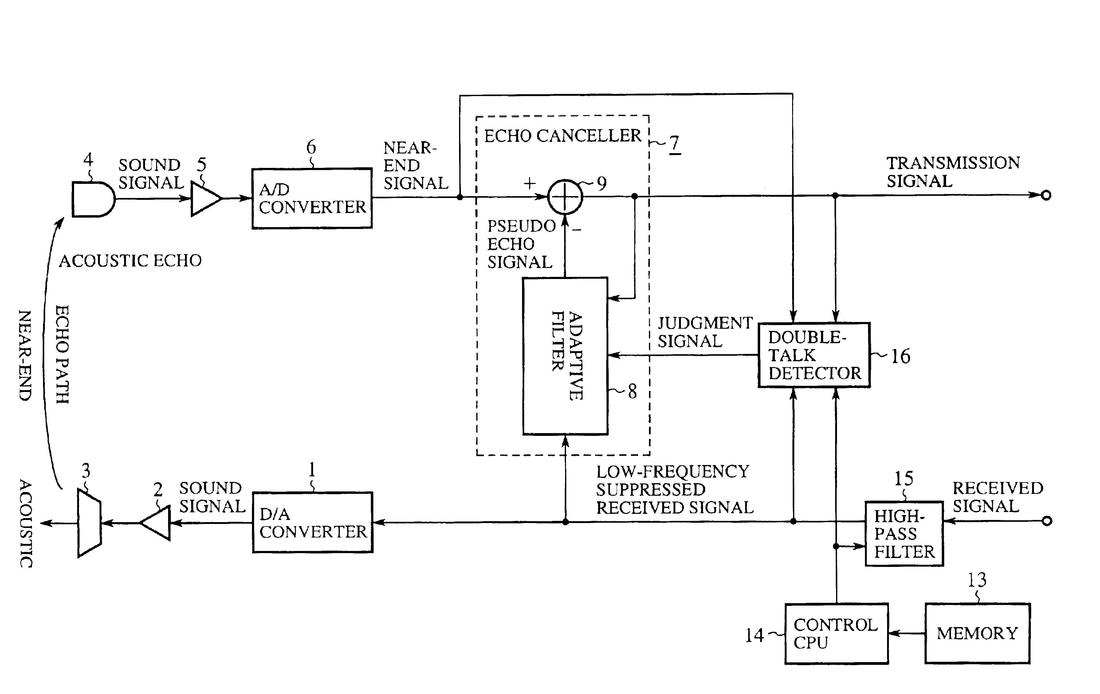
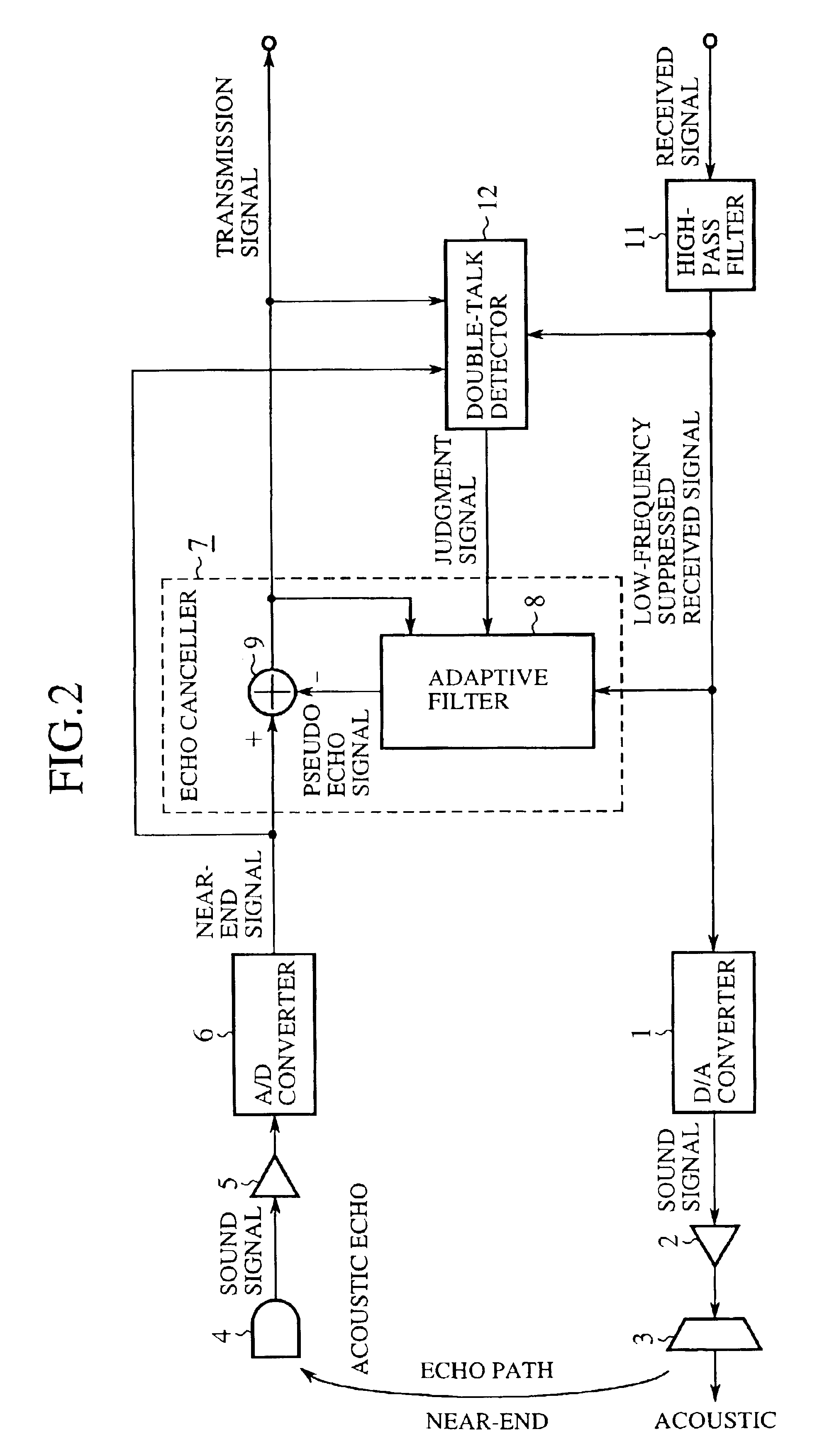
FIG. 2 is a circuit block diagram showing a configuration of an echo processor according to a first embodiment of the present invention. In the diagram, reference number 11 indicates a high-pass filter for suppressing a low-frequency component in a received signal in a digital form. Reference number 1 designates a digital to analogue (D / A) converter for converting the low-frequency suppressed received signal in digital form to an analogue sound signal, 2 denotes an amplifier for amplifying the sound signal, and 3 indicates a speaker for outputting the acoustic corresponding to the sound signal amplified. Reference number 4 designates a microphone for inputting the acoustic and converting it to a sound signal, 5 denotes an amplifier for amplifying the sound signal, and 6 indicates an analogue to digital (A / D) converter for converting the amplified sound signal to a digital signal. Reference number 7 designates an echo canceller for generating a pseudo echo signal based on the low-fre...

second embodiment

The double-talk detector 12 of the first embodiment performs to judge the double-talk when the following both cases:

The equation (4) is not satisfied and both the equations (5) and (7) are satisfied; and

Both the equations (4) and (5) are not satisfied and both the equations (6) and (7) are satisfied.

However, in a case when Rs is large, namely over 362, that is, when the background noise is smaller, the equation (4) is not satisfied and the equation (7) is satisfied. Accordingly, when the above condition is established, it is possible to judge the double-talk regardless of the result of both the equations (5) and (6). Accordingly, when the background noise is small, it is possible to judge the double-talk correctly even if S or E is small and to prevent the occurrence of the error detection where the case including the large background noise is judged as the double-talk.

As described above, according to the second embodiment, because the high-pass filter 11 suppresses the low-frequenc...

third embodiment

FIG. 4 is a circuit block diagram showing a configuration of an echo processor according to a third embodiment of the present invention. In the diagram, reference number 17 designates a noise suppressor. Other components are the same of those shown in FIG. 2. The double-talk detector 12 performs the same operation of that in the second embodiment.

Next, a description will now be given of the operation of the conventional echo processor.

The noise processor 17 inputs the near-end signal from the A / D converter 6 and suppresses the background noise component included in the near-end signal and outputs the near-end signal including the component other than the suppressed one.

There is a literature (Reference 4) that disclosed a spectral subtraction method as an example how to suppress the background noise component included in the near-end signal.

Reference 4: Steven F. Boll, “Suppression of Acoustic noise in speech using spectral subtraction”. IEEE Trans. ASSP. Vol. ASSP-27, No.2, April 19...


PUM


Abstract

An echo canceller has a high-pass filter 11, a speaker 3, an A/D converter 6, and an echo canceller 7. The high-pass filter 11 suppresses a low-frequency component in a received signal. The speaker 3 outputs an acoustic sound of a low-frequency suppressed received signal passed through the high-pass filter 11. The A/D converter 6 converts an acoustic echo from a microphone 4 into a transmission signal of a digital form. The echo canceller 7 generates a pseudo echo signal based on the low-frequency suppressed received signal passed through the high-pass filter 11, and eliminates the acoustic echo to be inputted to the microphone 4 from the speaker 3 by subtracting the pseudo echo signal from the digital signal converted by the A/D converter 6.

Description

TECHNICAL FIELDThe present invention relates to an echo processor for reducing an acoustic echo component outputted from a speaker inputted to a microphone transferred through an echo path in an acoustic communication using mobile units such as an on-vehicle telephone and a cellular phone.BACKGROUND ARTFIG. 1 is a block diagram showing a configuration of a circuit of a conventional echo processor. In the diagram, reference number 1 designates a digital to analogue (D / A) converter for converting a received signal in digital form to a sound signal in analogue form, 2 denotes an amplifier for amplifying the sound signal, and 3 indicates a speaker for outputting the acoustic corresponding to the sound signal amplified. Reference number 4 designates a microphone for inputting an acoustic and converting it to a sound signal, 5 denotes an amplifier for amplifying the sound signal, and 6 indicates an analogue to digital (A / D) converter for converting the amplified sound signal to a digital ...

Claims


Application Information

Patent Timeline
Patent Type & Authority Patents(United States)
IPC IPC(8): G10L21/00G10L21/02H04R3/02H04M1/60H04M19/08H04M9/08H04M1/725H04M1/72G10L21/0208
CPCH04R3/02H04M9/082H04M19/08G10L2021/02082H04M1/6033H04M1/725
Inventor TAKAHASHI, SHINYAMATSUOKA, BUNKEIKAJIYAMA, IKUO
Owner MITSUBISHI ELECTRIC CORP
Why Eureka
Try Eureka