Satellite constellation system

a satellite constellation and satellite technology, applied in the field of asymmetrical constellations of manmade satellites, can solve the problems of increasing the cost of satellite launch to the necessary geo altitude, increasing the cost of providing continuous access, so as to and increase the continuous access time of asymmetrical satellite constellations

Inactive Publication Date: 2005-03-15
LOCKHEED MARTIN CORP
View PDF12 Cites 38 Cited by
  • Summary
  • Abstract
  • Description
  • Claims
  • Application Information

AI Technical Summary

Benefits of technology

In view of the foregoing, a broad objective of the present invention is to increase the continuous access time of satellite constellations. Another objective of the present invention is to increase the continuous access time of asymmetrical satellite constellations. A further objective is to increase the continuous access time of asymmetrical satellite constellations with a relatively small number of satellites.

Problems solved by technology

One disadvantage of GEO satellites is that it is much more expensive to launch the satellite to the necessary GEO altitude as compared to satellites at lower altitudes.
Another disadvantage is that a sensor deployed on a GEO satellite would have to be more capable than its LEO counterpart to maintain the desired accuracies over the longer ranges.
Providing continuous access can be very expensive, however, as many satellites can be required.
Unfortunately, by distributing a limited number of satellites in a symmetric pattern to minimize gap times, access is limited to the duration that a single satellite can see a given ground point.
Therefore, if it is desired to continuously monitor a given ground point for a longer period of time (for example, 30 minutes), it may not be possible unless an entirely populated, symmetrical constellation is provided with a great number of satellites to provide continuous access.

Method used


Image

  • Satellite constellation system
  • Satellite constellation system
  • Satellite constellation system

Examples


first embodiment

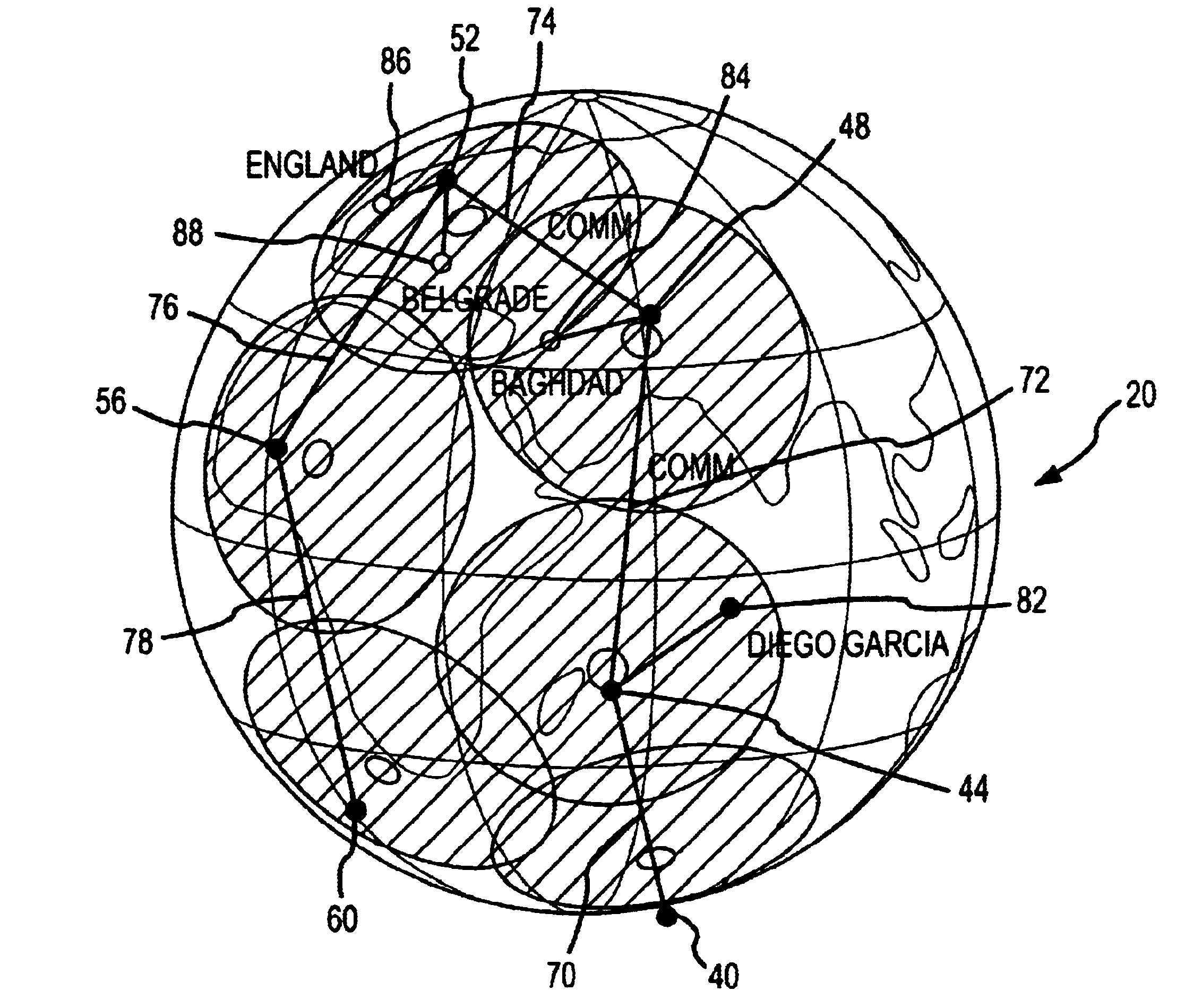
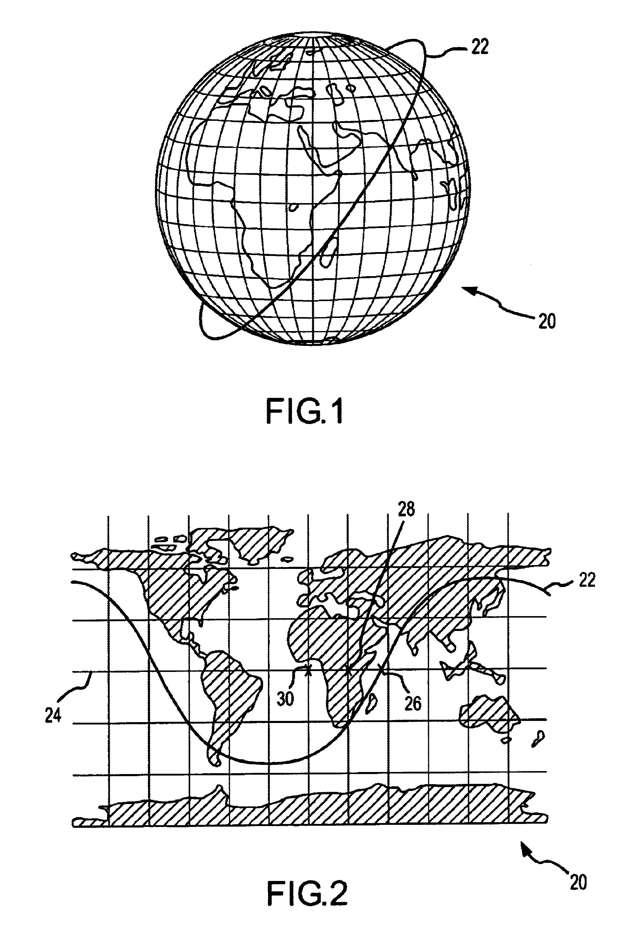
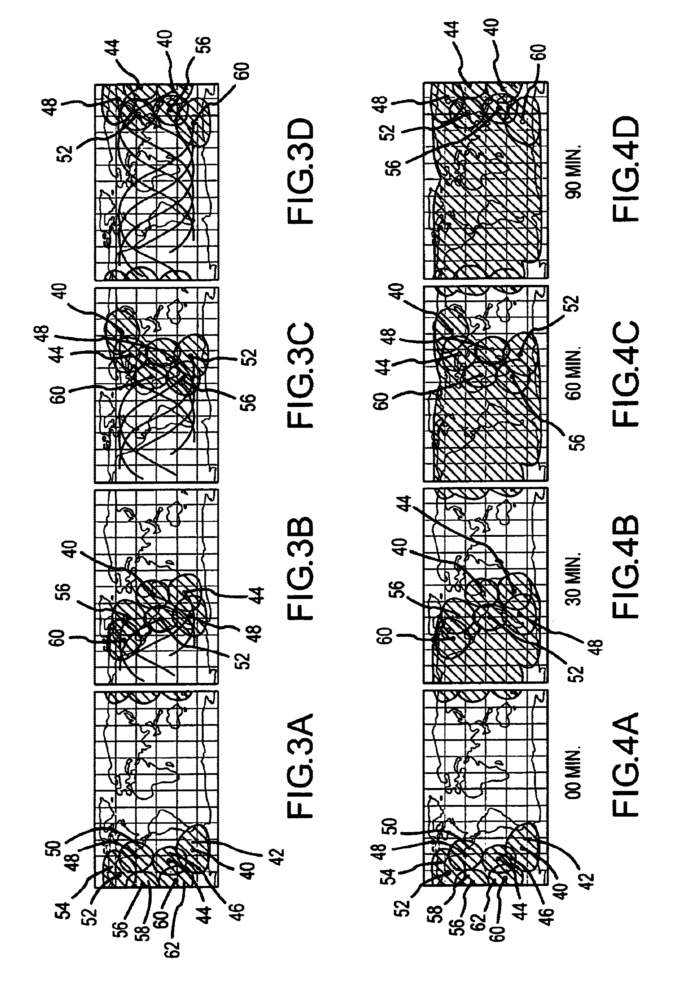
the satellite positioning system of the present invention is shown in FIGS. 3A-3D. In this two-dimensional projection of the earth 20 shown in FIG. 3A, six satellites and their respective fields of regard are shown. First, a lead satellite 40 and its field of regard (FOR) 42 are shown, followed by a first trailing satellite 44 and its respective FOR 46, followed next by another trailing satellite 48 and its FOR 50, followed by another trailing satellite 52 and its FOR 54, followed by another trailing satellite 56 and its FOR 58, then followed by the last trailing satellite 60 and its FOR 62. The FORs may be the area that could be seen by space-based radar (SBR) that may be located on the satellites to perform such functions as determining Ground Moving Target Indication (GMTI) data, for example. FIG. 3B shows these six satellites at a subsequent time in their respective orbits (roughly 30 minutes later). The ground tracks for each of the six satellites showing the path covered by th...


PUM


Abstract

A satellite constellation system, including a plurality of satellites in relatively close proximity to each other so that line-of-sight communications can be maintained at all times between adjacent satellites. The satellites are in closely-spaced orbits with incremental offsets in their starting true anomalies to create a pattern of the satellites which is serpentine in nature, moving north and south through latitudes covered as a result of the selected inclination angle while moving also in a longitudinal direction so that the serpentine pattern moves across most ground regions of interest. The constellation is asymmetric in nature in order to maximize the continuous access time. It is also possible to have multiple symmetrically-located constellations of this type.

Description

FIELD OF THE INVENTIONThe present invention relates generally to constellations of man-made satellites, and more particularly to asymmetrical constellations of man-made satellites that allow for extended access to a ground point.BACKGROUND OF THE INVENTIONMan-made satellites orbiting around the earth are typically categorized as being in one of a geosynchronous earth orbit (GEO), a medium earth orbit (MEO), a low earth orbit (LEO), or a highly elliptical earth orbit (HEO). Each of these types of orbits has particular advantages and disadvantages, which take on relatively different importance depending on the application for which the satellite is being used.GEOs have the advantage that the satellite orbits at generally the same angular rate around the earth as the earth is rotating (approximately one orbit every 24 hours), so that the satellite appears to hover over a given ground point on the earth. This is achieved in part by having the satellite orbit near the earth's equator and...

Claims


Application Information

Patent Timeline
Patent Type & Authority Patents(United States)
IPC IPC(8): B64G1/10B64G1/24B64G1/00G05D1/08
CPCG05D1/0883B64G1/242B64G1/1085B64G1/1007B64G1/244
Inventor STEVENS, CRAIG W.
Owner LOCKHEED MARTIN CORP
Why Eureka
Try Eureka