Reaction chamber, deposition equipment and cleaning method suitable for remote plasma cleaning

A remote plasma and reaction chamber technology, applied in the field of semiconductor equipment, can solve problems such as structural component damage, and achieve the effects of reducing damage, avoiding component damage, and reducing damage

Active Publication Date: 2022-05-27
BEIJING NAURA MICROELECTRONICS EQUIP CO LTD
View PDF0 Cites 0 Cited by
  • Summary
  • Abstract
  • Description
  • Claims
  • Application Information

AI Technical Summary

Problems solved by technology

[0006] The purpose of the present invention is to propose a reaction chamber, deposition equipment and cleaning method suitable for remote plasma cleaning, to solve the problem of damage to structural components inside the reaction chamber when cleaning the chamber

Method used


Image

  • Reaction chamber, deposition equipment and cleaning method suitable for remote plasma cleaning
  • Reaction chamber, deposition equipment and cleaning method suitable for remote plasma cleaning

Examples


Embodiment 1

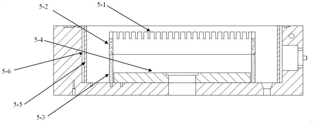
[0044] Embodiment 1 of the present invention provides a reaction chamber suitable for remote plasma cleaning, figure 1 A schematic structural diagram of a reaction chamber suitable for remote plasma cleaning according to Embodiment 1 of the present invention is shown, please refer to figure 1 , the reaction chamber includes:

[0045] cavity body;

[0046] The heating base 5-4 is arranged in the main body of the cavity.

[0047] The annular support member 5-3, the annular support member 5-3 surrounds the outer circumference of the heating base 5-4, the surface of the annular support member 5-3 facing the heating base 5-4 is the inner surface, and the surface facing the heating base 5-4 The surface of 4 is the outer surface, the roughness of the outer surface is greater than that of the inner surface, and the material of the annular support member 5-3 is ceramic.

[0048] The gas distribution grid 5-2 is arranged on the annular support member 5-3 and is located above the heat...

Embodiment 2

[0054] Embodiment 2 of the present invention provides a deposition apparatus, which includes the above-mentioned reaction chamber, and further includes: a plasma cleaning source chamber;

[0055] a cleaning pipeline, which is connected between the plasma cleaning source chamber and the reaction chamber;

[0056] The air source pipeline is connected to the cleaning pipeline.

[0057] Specifically, the plasma cleaning source chamber is used to generate excited plasma, and the generated plasma enters the reaction chamber through the cleaning pipeline to clean the interior of the reaction chamber. The gas source pipeline is used for supplying the reaction gas to the plasma cleaning source chamber, and feeding the purging gas into the cleaning pipeline, and the purging gas purifies the interior of the reaction chamber after cleaning the reaction chamber.

Embodiment 3

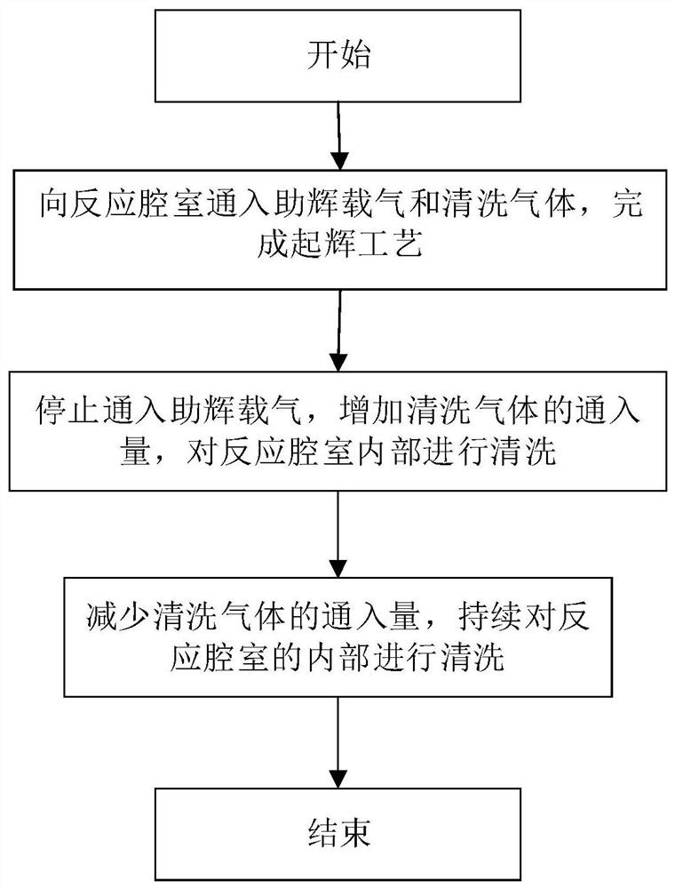
[0059] Embodiment 3 of the present invention provides a cleaning method for a deposition device, comprising the following steps:

[0060] Step 1: Pass the booster carrier gas and the cleaning gas into the plasma cleaning source chamber through the gas source pipeline, wherein the booster carrier gas is argon, so as to enhance the ignition in the plasma cleaning source chamber; The glow carrier gas and the cleaning gas are used to complete the ignition process.

[0061] Step 2: After the ignition process is completed, stop the introduction of the boosting carrier gas and increase the amount of cleaning gas. The cleaning gas is excited by the plasma cleaning source chamber to form plasma, and the plasma enters the reaction chamber through the cleaning pipeline , to clean the interior of the reaction chamber.

[0062] Step 3: reduce the flow of cleaning gas, and continuously clean the interior of the reaction chamber.

[0063] Specifically, in step 1, first, a booster carrier g...


PUM

PropertyMeasurementUnit
surface roughnessaaaaaaaaaa

Abstract

The invention discloses a reaction chamber, deposition equipment and cleaning method suitable for remote plasma cleaning, wherein the reaction chamber comprises: a chamber main body; a heating base, which is arranged in the chamber main body; an annular supporting part , the annular support member surrounds the outer periphery of the heating base, the surface of the annular support member facing the heating base is the inner surface, and the surface facing away from the heating base is the outer surface, the roughness of the outer surface is greater than the roughness of the inner surface, and the ring support The material of the component is ceramic; the gas uniform flow grid is arranged on the annular support component and is located above the heating base. The deposition equipment includes: the above-mentioned reaction chamber; the plasma cleaning source chamber; the cleaning pipeline, which is connected between the plasma cleaning source chamber and the reaction chamber; the gas source pipeline, which is connected to the Clean the lines. The beneficial effect of the present invention is that it can solve the problem of damage to structural components inside the reaction chamber when cleaning the chamber.

Description

technical field [0001] The present invention relates to the field of semiconductor equipment, and more particularly, to a reaction chamber suitable for remote plasma cleaning, deposition equipment and cleaning method. Background technique [0002] Plasma-enhanced atomic layer deposition (PEALD) is a process that enhances the traditional atomic layer deposition process by creating a plasma with more atoms and molecules in high-energy chemical states. For deposition such as silicon dioxide (SiO2), silicon nitride (Si3N4), silicon oxynitride (SiON), etc. [0003] In the production process of Plasma Enhanced Atomic Layer Deposition (PEALD), the interior of the reaction chamber needs to be cleaned regularly to avoid the resulting contamination affecting the performance of the thin film. Existing cleaning processes mainly include chemical cleaning, in-situ plasma cleaning, remote plasma source (remote plasma source, RPS) cleaning, and the like. [0004] Remote plasma cleaning is...

Claims


Application Information

Patent Timeline
Patent Type & Authority Patents(China)
IPC IPC(8): C23C16/44C23C16/455C23C16/513
CPCC23C16/4405C23C16/45544C23C16/513
Inventor 秦海丰史小平兰云峰王勇飞纪红赵雷超张文强
Owner BEIJING NAURA MICROELECTRONICS EQUIP CO LTD
Why Eureka
Try Eureka