
Outlet arrangement for down-hole separator

a separator and outlet arrangement technology, applied in the direction of separation process, drilling pipe, borehole/well accessories, etc., can solve the problems of water entering the oil phase and oil entering, and the residence time alone is not enough, so as to facilitate the coalescing and migration of smaller droplets, the effect of decreasing the cross sectional area and increasing the total residence tim

Inactive Publication Date: 2005-03-22
AKER SUBSEA LTD
View PDF8 Cites 21 Cited by
  • Summary
  • Abstract
  • Description
  • Claims
  • Application Information

AI Technical Summary

Benefits of technology

It is therefore an object of the present invention to ensure that each of the phases is distributed to the appropriate outlet without interfering with the oil-water interface and re-mixing the phases. As the phases exist in a separated state as much as several meters before the end of the separator, each of them should be extracted gradually over a certain distance before the end wall of the separator. Through such gradual extraction of separated fluids, the residence time for the remaining liquid in the separator will be extended, allowing the smaller oil and water droplets to migrate to the oil and water phases respectively. This is achieved by a two phase liquid / liquid separator in which the oil and water phases respectively are separated over at least part of the length of the separator from an upstream end to a downstream end of the separator wherein the oil and water phases are respectively are extracted gradually over a length of the separator, the length extending substantially all the way from the downstream separator and wherein the oil and water phases respectively are extracted substantially symmetrically respective to longitudinal axis of the separator and wherein each of the phases is extracted from the separator separately. This is further achieved by an arrangement at a separator for separating oil from water, the arrangement including a separator chamber with an upstream and a downstream end and an oil outlet and a water outlet, the water outlet being situated in an upper part of the separator chamber and the oil outlet being situated in a lower outlet of the separator chamber wherein the oil and water outlet are respectively distributed over a length of the separator at the downstream end of this and wherein the oil and water outlets, with respect to each other, are arranged substantially symmetrically relative to the longitudinal axis of the separator.
In the case of an outlet arrangement of the type with which the present invention is concerned, it is important for the separator to have the correct orientation, so that the oil outlets face upwards and the water outlets face downwards. According to the present invention, a method and an arrangement have therefore been provided in order to achieve this. The method is characterised by orienting an outlet arrangement in a horizontal downhole separator such that a guide device is inserted into a hole and fixed relative to the hole, inserting a measuring tool into the hole in order to register the orientation of first guide means on the guide device, setting second guide means on the separator, the second guide means corresponding to the first guide means, in accordance with the orientation of the first guide means, inserting the separator with the outlet arrangement into the hole, and rotating the separator to a predetermined lintation upon contact between the first and second guide means. When oil and water are extracted from the separator over a certain distance, the effect on the interface is lessened. It becomes easier to avoid extracting liquid from the area near the interface. Small, dispersed droplets of the opposite phase will often be present near the interface, e.g. water droplets in the oil phase and oil droplets in the water phase. These droplets will be given more time to coalesce and migrate to the phase to which they belong.
By such an arrangement, clean oil and water may be collected as early as possible upon becoming accessible, and then be transported out of the separator via the outlet pipe. Any disturbance of the liquid phases will be minimal when oil and water are removed over an extended distance. By constructing outlet slots or holes with a decreasing cross sectional area in the downstream direction, the velocity of the liquid in the outlet pipe will increase in the downstream direction. The acceleration is preferably linear. When the clean oil and water are brought out at a higher velocity than the mean bulk velocity in the separator, the total residence time is increased, making it easier for smaller droplets to coalesce and migrate.

Problems solved by technology

A large oil-water interface and sufficient residence time alone is not enough to achieve clean oil and water phases at the outlet of the separator.
Since the diameter of the outlet is small, this will easily influence the oil-water interface and thereby result in water entering the oil phase and oil entering the water phase.

Method used


Image

  • Outlet arrangement for down-hole separator
  • Outlet arrangement for down-hole separator
  • Outlet arrangement for down-hole separator

Examples


Embodiment Construction

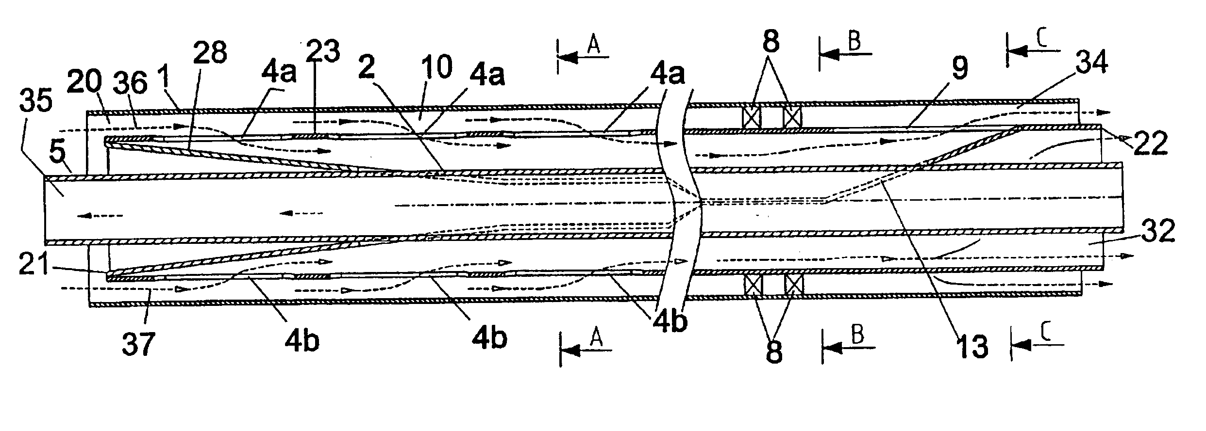
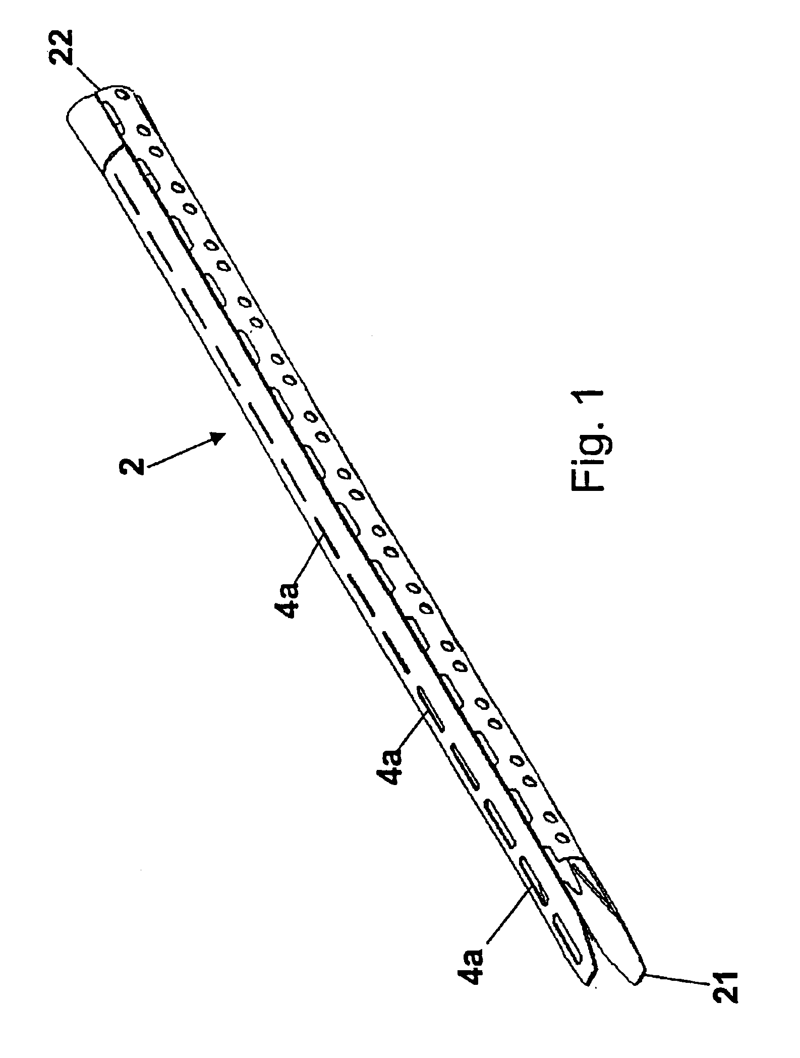
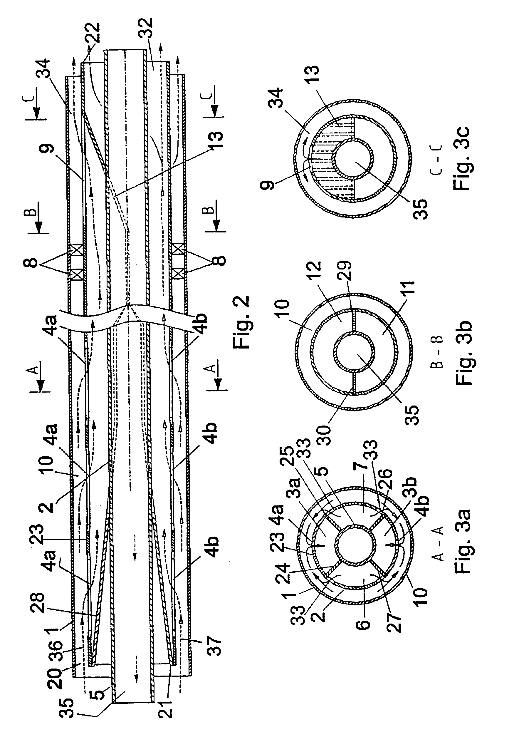
FIGS. 2 and 3a, b, and c show a longitudinal and transverse sections respectively through part of a liquid-liquid separator according to the present invention and including the outlet arrangement shown in FIG. 1. The separator has a high length to diameter ratio.

The separator comprises a separator wall 1 tubularly enclosing a separator chamber 20. An outlet arrangement 2 is provided inside the separator chamber 20. The outlet arrangement 2 is positioned along the longitudinal axis of the separator chamber 20, and extends over a length of e.g. 2-4 meters at the downstream end of the separator.

The outlet arrangement 2 has an outer end 21 facing the upstream direction and an inner end 22 that is connected to transport conduits outside the separator (not shown). The outlet arrangement further comprises an outer wall 23 that forms a pipe having approximately the same cross section along the length of the outlet arrangement 2. An annulus 10 is defined between the separator wall 1 and the ...


PUM


Abstract

A method and an arrangement for separating oil and water by means of a two-phase liquid / liquid separator. The oil phase and the water phase respectively are separated over a portion of the length of the separator from an upstream end to a downstream end. The oil phase and the water phase respectively are extracted gradually over a length of the separator, and each of the phases is conducted out of the separator separately. A method and an arrangement for orienting the separator in a well are also described.

Description

BACKGROUND OF THE INVENTION1. Field of the InventionThe invention regards an outlet arrangement for use in separation of water and oil by means of a two-phase liquid / liquid separator in which the oil and water phases are respectively separated over at least part of the length of the separator from an upstream end to a downstream end of the separator. In particular, the invention regards an outlet arrangement for a horizontal gravity separator with a high length / diameter ratio. The invention especially regards a downhole separator for placing in an underground well. The invention also regards a method for inhibiting re-mixing of the oil and water phases in a separator where the separator includes a separator chamber with an upstream end and a downstream end and an oil outlet and a water outlet, the water outlet being situated in an upper part of the separator chamber and the oil outlet being situated in a lower part of the separator chamber.The invention also regards a method for ori...

Claims


Application Information

Patent Timeline
Patent Type & Authority Patents(United States)
IPC IPC(8): B01D17/02E21B43/34E21B43/38B01D17/025
CPCB01D17/0208E21B43/38B01D17/0211B01D17/0214B01D17/04
Inventor HOMSTVEDT, GUNDEROLSEN, GEIR INGEDANIELSEN, BJ.O SLASHED.RNAR
Owner AKER SUBSEA LTD
Features
  • Generate Ideas
  • Intellectual Property
  • Life Sciences
  • Materials
  • Tech Scout
  • Unparalleled Data Quality
  • Higher Quality Content
  • 60% Fewer Hallucinations
Learn More