Nickel metal particle production
A particle and metal technology, applied in the direction of metal/metal oxide/metal hydroxide catalyst, catalyst activation/preparation, organic compound/hydride/coordination complex catalyst, etc., can solve problems such as hazards
- Summary
- Abstract
- Description
- Claims
- Application Information
AI Technical Summary
Problems solved by technology
Method used
Image

Examples
example 1
[0139] Example 1: Calcination of Basic Nickel Carbonate
[0140] This example illustrates the use of air or nitrogen for calcination of basic nickel carbonate obtained from commercial source A.
[0141] Basic nickel carbonate was calcined in a batch rotary processor at 450°C with a gas flow rate of 3 L / min pure gas (air or nitrogen). When calcination (BK1) is carried out in air, basic nickel carbonate is calcined until carbon dioxide (CO 2 ) 15 minutes after the concentration reaches zero.
[0142] When calcination (BK2) is carried out under nitrogen, basic nickel carbonate is calcined until CO 2 Two hours after the concentration reaches zero.
[0143] When nitrogen is used, the calcined basic nickel carbonate product has a distinctive brown color and is black when air calcined. The yellow to brown color of the nitrogen calcined product did not change with exposure to air at room temperature.
[0144] In the second experiment, basic nickel carbonate was calcined in nitrog...
example 2
[0154] Example 2: Reduction of NiO using steam in hydrogen
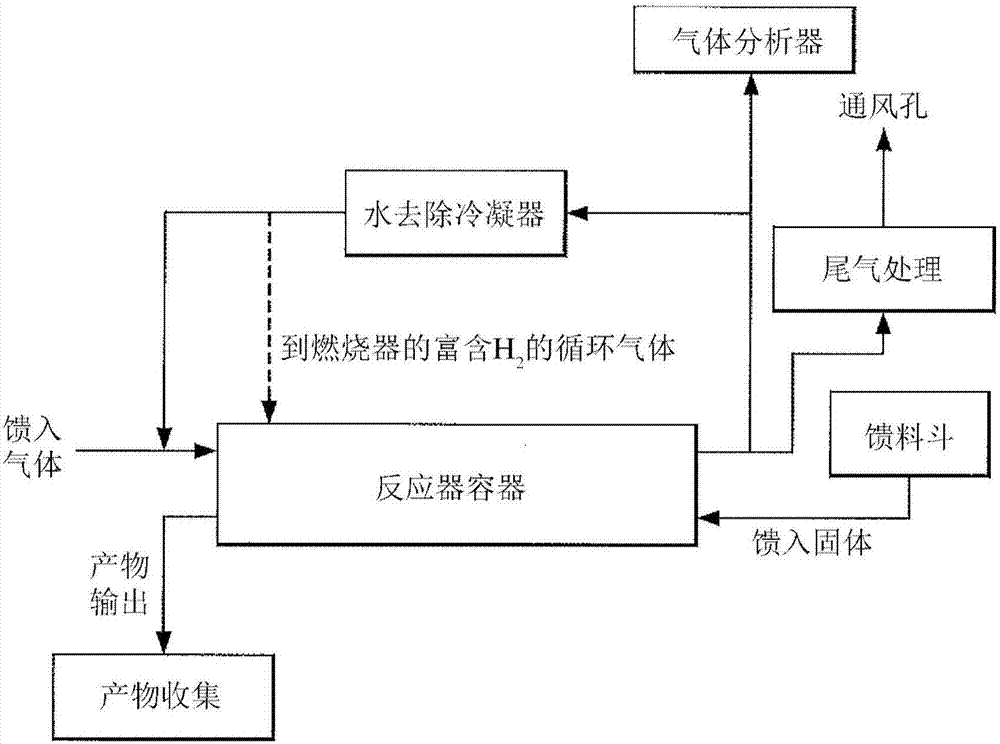
[0155] This example describes another experiment exploring the reduction of NiO by hydrogen in the presence of steam within a spin processor. The NiO for these experiments was produced by calcination of basic nickel carbonate from either commercial source A or commercial source B. The contact between the two phases (ie solid and gas) is achieved in a batch rotating bed. The system operates in a semi-batch mode, where a quantity of raw material charged into the kiln is continuously exposed to a flowing reaction gas.
[0156] In a first experiment (BK4), nickel oxide (250 g) was produced by calcining BNC from commercial source A. Nickel oxide was reduced in a spin processor at 350°C in an atmosphere of 10% hydrogen and 30% steam and the balance nitrogen. Add steam gradually (approximately 0.25 L increments every 1-2 minutes). The flow rate of the atmosphere through the spin processor was 3-6 L / min. The rotation sp...
example 3
[0171] Example 3: Reduction of nickel in a spin processor without steam
[0172] This example shows that nickel oxide (NiO) is more efficiently reduced in a spin processor in an atmosphere without the use of steam.
[0173] In a first experiment (BK8), nickel oxide obtained from commercial source A was reduced in a spin processor at 350° C. in an atmosphere of 70% hydrogen and 30% nitrogen without addition of steam or water. The material in the rotary reactor was initially free flowing, but then appeared slightly cohesive. Material builds up along the reactor walls until it spins to the top of the reactor, at which point the material falls under its own weight. Eventually, the material becomes less cohesive over time and begins to roll freely.
[0174] The reduction of this first experiment was completed within 1.25 hours. The final product was free flowing and, although some pebbles were present, most were below 0.25 inches in size. Initially, the smaller pebbles (approxi...
PUM
| Property | Measurement | Unit |
|---|---|---|
| size | aaaaa | aaaaa |
| diameter | aaaaa | aaaaa |
Abstract
Description
Claims
Application Information
 - Generate Ideas
- Intellectual Property
- Life Sciences
- Materials
- Tech Scout
- Unparalleled Data Quality
- Higher Quality Content
- 60% Fewer Hallucinations
Browse by: Latest US Patents, China's latest patents, Technical Efficacy Thesaurus, Application Domain, Technology Topic, Popular Technical Reports.
© 2025 PatSnap. All rights reserved.Legal|Privacy policy|Modern Slavery Act Transparency Statement|Sitemap|About US| Contact US: help@patsnap.com