Electric clamping device

a technology of clamping device and electric clamping, which is applied in the direction of positioning apparatus, metal-working machine components, manufacturing tools, etc., can solve the problems of increasing cost, complicated piping operation, and limited installation space, so as to reduce cost, increase thrust, and simple structure of speed reducing mechanism

Inactive Publication Date: 2005-03-22
SMC CORP
View PDF28 Cites 22 Cited by
  • Summary
  • Abstract
  • Description
  • Claims
  • Application Information

AI Technical Summary

Benefits of technology

It is an object of the present invention to solve the above problems and to provide a small low-cost electric clamping device without problems associated with air piping and in which a toggle mechanism can be actuated by a small low-torque electric motor and which has a large clamping force while saving energy.
It is another object of the invention to provide an electric clamping device in which a varying manner of a clamping force immediately before a clamping position can be set arbitrarily by simple means, i.e., a slight change in cam rail faces.
In such an electric clamping device of the invention, because the speed reducing mechanism is formed of the multistage spur gears only, a structure of the speed reducing mechanism becomes simple and a cost can be reduced. Because a speed of the crank mechanism for converting the rotational motion of the spur gear into the linear motion is reduced near the end of a stroke to increase a thrust, it is possible to clamp a workpiece with a large force by actuating the toggle mechanism by a small low-torque motor.
Furthermore, in the electric clamping device of the invention, the linkage is formed of the crank link connected to the last-stage spur gear, the cam follower link having the cam follower moving on the cam rail face, and the driving lever connected to the tip end of the cam follower link, the toggle linkage is formed of them, and output torque while the clamp arm rotates from the fully-open position to the fully-closed position can be set arbitrary by the shape of the cam rail face. Therefore, it is possible to output an appropriate clamping force, e.g., suddenly increase the clamping force near the clamping position in spite of small average output torque. Because a reaction force from the workpiece when the workpiece is clamped is received by the cam rail face provided to the body, it is possible to reduce a reaction force applied to the crank mechanism and the speed reducing mechanism.

Problems solved by technology

However, the prior-art clamping device requires air piping.
A piping operation is complicated, a space for installation is limited by a plurality of tubes used for the air piping, the device is upsized, and a cost is increased due to an air leakage and the like.
Because a speed reducing mechanism is formed of the gear mechanism and the feed screw mechanism, a structure of the speed reducing mechanism is complicated and a cost is high.

Method used


Image

  • Electric clamping device
  • Electric clamping device
  • Electric clamping device

Examples


Embodiment Construction

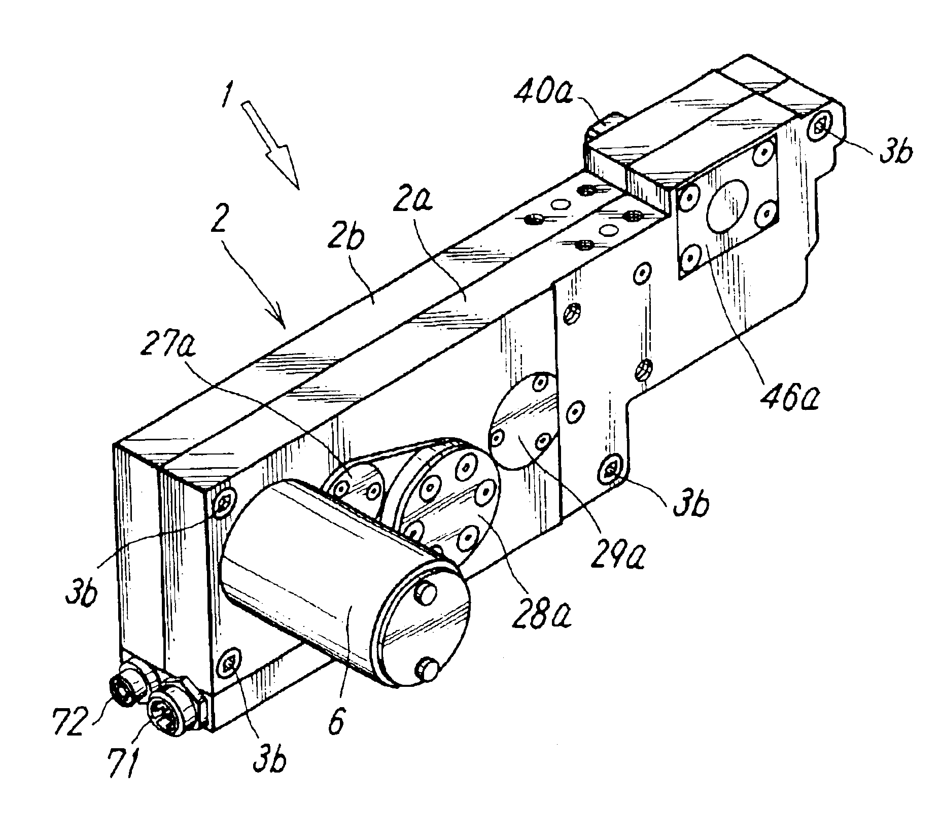
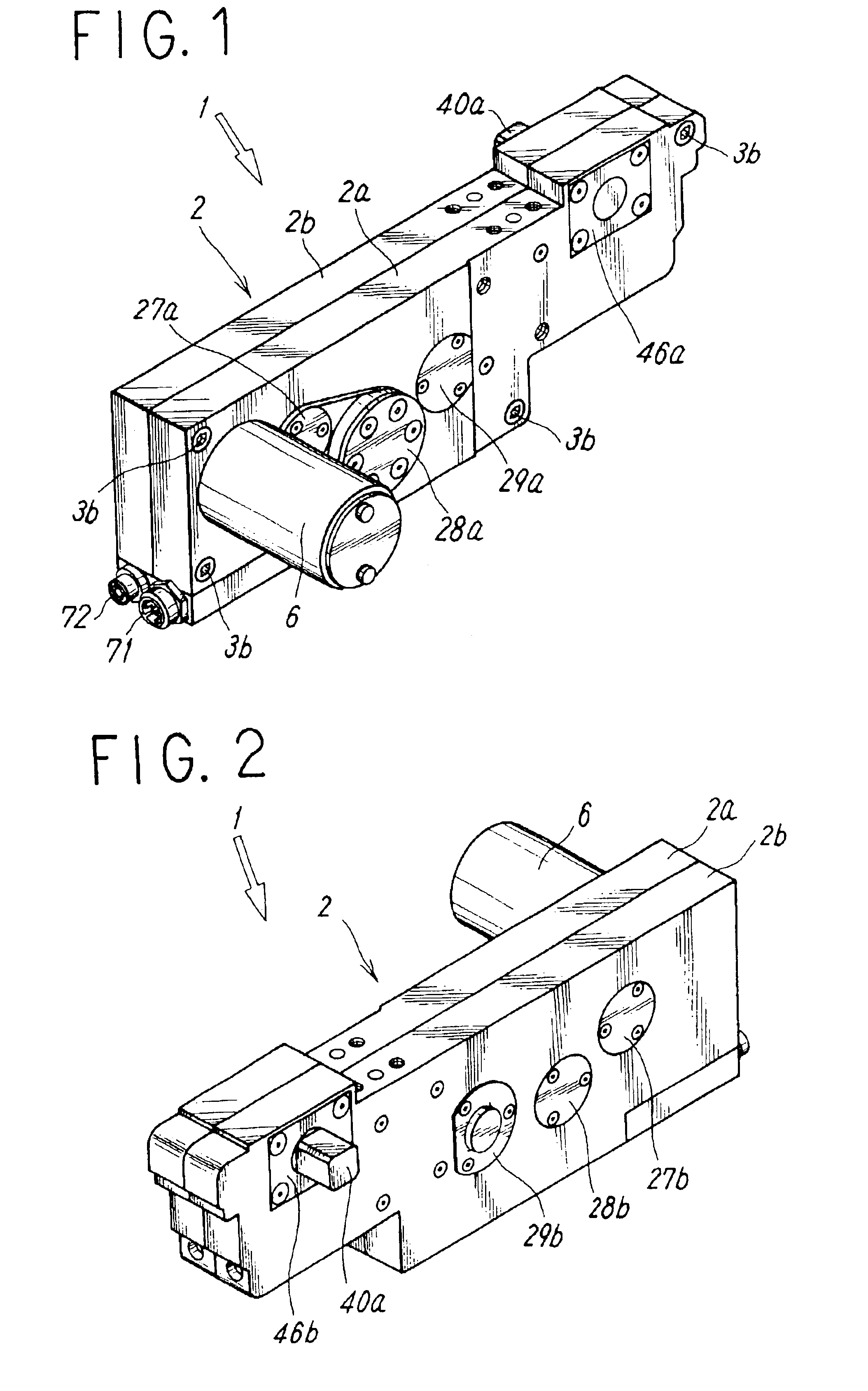
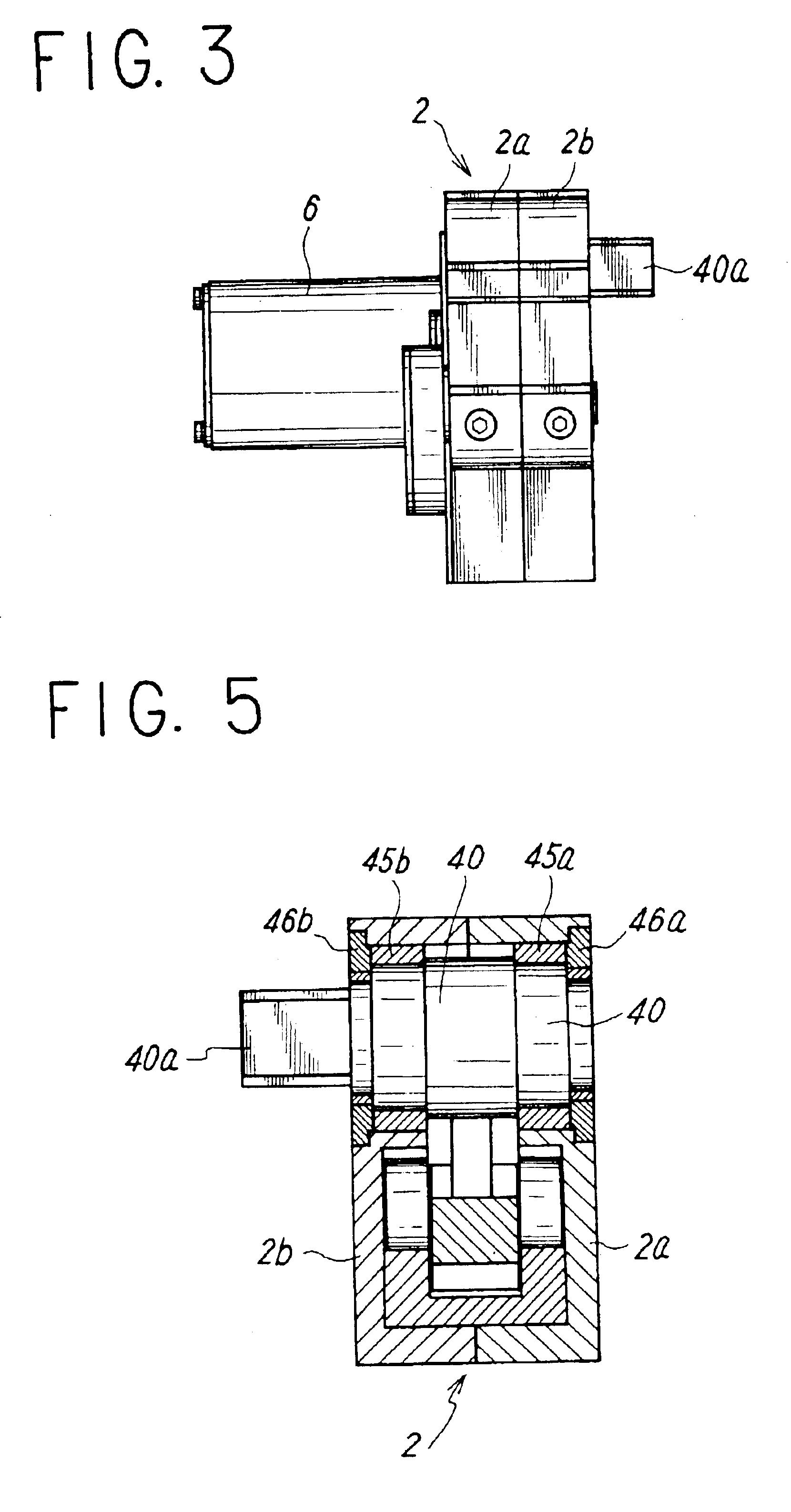
FIGS. 1 to 8 show an embodiment of an electric clamping device according to the present invention. The electric clamping device 1 has a thin body 2 substantially in a shape of a rectangular parallelepiped. The body 2 is formed of first and second body pieces 2a and 2b having opposed wall faces and peripheral wall faces. The first and second body pieces 2a and 2b are coupled by screwing a plurality of coupling bolts 3b down into screw holes 3a provided to corner portions of the second body piece 2b from an outer face side of the first body piece 2a to form a housing space 4 surrounded with the wall faces of the first and second body pieces 2a and 2b inside the body 2.

At an end portion of the first body piece 2a of the body 2, a recessed portion 3c for housing a head portion of an electric motor 6 and a hole through which an output shaft 6a of the electric motor 6 is inserted are provided. The output shaft 6a of the electric motor 6 is inserted through the hole into the housing space ...


PUM


Abstract

The present invention provides a low-cost electric clamping device in which a toggle linkage can be actuated by a small low-torque electric motor. The device includes a gear speed reducing mechanism connected to the electric motor, a linkage connected to the speed reducing mechanism, a clamp arm shaft connected to the linkage, and a body 2 for housing them. The linkage includes a crank link connected to a last-stage spur gear of the speed reducing mechanism, a cam follower link which is connected at one end thereof to the crank link and to which a cam follower moving on cam rail faces is rotatably mounted, and a driving lever to which the other end of the cam follower link is connected and which projects from the clamp arm shaft.

Description

TECHNICAL FIELD OF THE INVENTIONThe present invention relates to an electric clamping device for clamping a workpiece for a purpose of working and the like.PRIOR ARTIn an automatic assembly line or the like in the automobile industry, a clamping device for clamping a workpiece for a purpose of working is used frequently. A fluid pressure cylinder is used conventionally as a driving source for driving the clamping device and a clamp arm is rotated by a driving force of an air cylinder, for example, to generate a clamping force.However, the prior-art clamping device requires air piping. A piping operation is complicated, a space for installation is limited by a plurality of tubes used for the air piping, the device is upsized, and a cost is increased due to an air leakage and the like.To cope with such problems, there is a known electric clamping device in which an electric motor is used as a driving source (e.g., a specification of U.S. Pat. No. 6,354,580).In the above known electric...

Claims


Application Information

Patent Timeline
Patent Type & Authority Patents(United States)
IPC IPC(8): B25B5/00B25B5/06B25B5/08B25B5/12
CPCB25B5/06B25B5/122B25B5/087
Inventor ZHAO, KAISAMRAH, TOM FREDERICKKOZLOWSKI, JEFF GERALDRUDAITIS, ERICK WILLIAM
Owner SMC CORP
Why Eureka
Try Eureka